Sanitation vehicle

A sanitation vehicle and sanitation technology, applied in the field of sanitation vehicles, can solve the problems of large impact force of trash cans, easily damaged trash cans, and small payload, achieving the effect of large effective space, good sealing effect, and large payload

Active Publication Date: 2018-01-02
HUNAN JINSONG AUTOMOBILE CO LTD
View PDF7 Cites 0 Cited by
  • Summary
  • Abstract
  • Description
  • Claims
  • Application Information

AI Technical Summary

Problems solved by technology

[0002] The feeding device of the currently used sanitation car, its lifting mechanism uses a hydraulic cylinder and a chain to cooperate with each other to push the slide plate and the trash can to rise in a straight line. , high energy consumption, large impact force when the trash can is turned over, easy to damage the trash can
On the other hand, the front end of the sanitation car needs to reserve space for installing the lifting mechanism, resulting in a small effective space for carrying goods in the sanitation car, and a small effective load, which is inconvenient

Method used


Image

  • Sanitation vehicle
  • Sanitation vehicle
  • Sanitation vehicle

Examples


Embodiment Construction

[0023] The present invention is described in detail below in conjunction with accompanying drawing and specific embodiment:

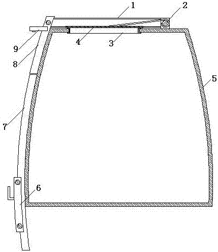
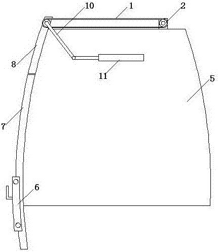
[0024] Such as figure 1 , figure 2 , image 3As shown, the sanitation vehicle of the present invention, the sanitation vehicle, also includes a feeding device and a discharging device, and the feeding device includes a sanitation compartment 5 , guide rails 7 , lifting frame 6 , and rotating frame 8 . Sanitation compartment 5 top is provided with garbage inlet 3, rear end opening. The bottom of the sanitation compartment 5 rear end is connected with the main frame rear end of the transport vehicle by the first hinge. Guide rail 7 is fixedly connected with environmental sanitation compartment 5 sidewalls, and the height between the bottom end of this guide rail 7 and the ground adapts to the garbage bin or dustbin placed on the ground. The lifting frame 6 is provided with a buckle and is slidably connected with the guide rail 7, and is used for tran...


PUM


Abstract

The invention discloses a sanitation vehicle. The sanitation vehicle comprises a feeding device and a discharging device. The feeding device comprises a sanitation compartment, a guide rail, a lifting frame and a rotary frame, the top of the sanitation compartment is provided with a garbage inlet, and the rear end of the sanitation compartment is open. The guide rail is fixedly connected with the lateral wall of the sanitation compartment. The lifting frame is provided with a hanging buckle and is in sliding connection with the guide rail. The bottom end of the rotary frame is connected with the top end of the guide rail, and the top end of the rotary frame is arranged near the garbage inlet of the top of the sanitation compartment and is hinged to the garbage inlet. The discharging device comprises a door and an automatic door opening system. The door is arranged at the rear end of the sanitation compartment. A sealing groove is formed in the position, corresponding to the opening in the rear end of the sanitation compartment, of the door. The automatic door opening system comprises a rotary arm and a first hydraulic cylinder. The rotary arm is connected with the lateral wall of the sanitation compartment through a hinge pin. One end of the rotary arm is fixedly connected with the door, and the other end of the rotary arm is connected with the top end of a piston rod of the first hydraulic cylinder.

Description

technical field [0001] The invention relates to a sanitation transportation device, in particular to a sanitation vehicle. Background technique [0002] The feeding device of the currently used sanitation car, its lifting mechanism uses a hydraulic cylinder and a chain to cooperate with each other to push the slide plate and the trash can to rise in a straight line. , The energy consumption is large, and the impact force is large when the trash can is turned over, which is easy to damage the trash can. On the other hand, the front end of the sanitation car needs to reserve the space for installing the lifting mechanism, resulting in a small effective space for carrying goods in the sanitation car, and a small effective load, which is inconvenient. Contents of the invention [0003] The technical problem to be solved by the present invention is to provide a sanitation vehicle that is easy to use, small in size, and does not require installation space at the front end of th...

Claims


Application Information

Patent Timeline
Patent Type & Authority Patents(China)
IPC IPC(8): B65F3/00
Inventor 赵正义
Owner HUNAN JINSONG AUTOMOBILE CO LTD
Why Eureka
Try Eureka