

Intercooler pipeline fixing structure
A fixed structure, cooler technology, applied in machine/engine, combustion engine, non-rotational vibration suppression, etc., can solve problems such as large swinging body, and achieve the effect of uniform force
- Summary
- Abstract
- Description
- Claims
- Application Information
AI Technical Summary
Problems solved by technology
Method used
Image

Examples
Embodiment Construction
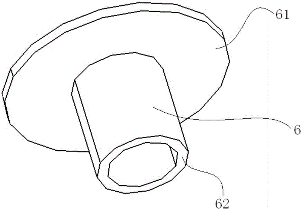
[0025] refer to figure 2 , The top end of the steel sleeve 6 used in this embodiment has a flange 61 .
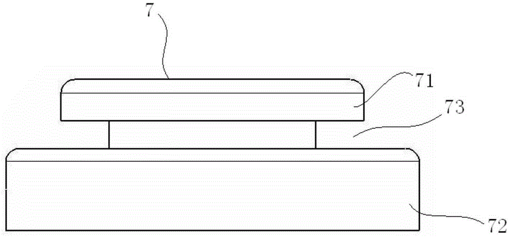
[0026] refer to image 3 , Figure 4 with Figure 5 , The cushion 7 used in this embodiment has an upper flange 71 , a lower flange 72 and a first annular groove 73 between the upper flange 71 and the lower flange 72 . The opening of the first ring groove 73 is located at the side of the cushion 7 . from Figure 4 and Figure 5 It can be seen more clearly that the lower flange 72 has a plurality of concentric second annular grooves 74 with openings located on the bottom surface of the cushion 7,
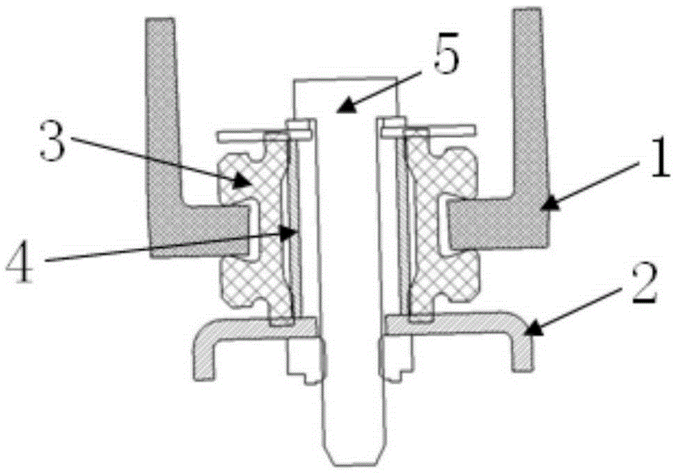
[0027] refer to Image 6 with Figure 7 , the intercooler pipeline fixing structure in this embodiment includes: an intercooler pipeline bracket 1 for fixing the intercooler pipeline, an engine fixing bracket 2 for supporting the intercooler pipeline on the engine, Bolt 5, steel sleeve 6 and cushion 7. The height of the soft pad 7 is greater than the height of the lower...
PUM
| Property | Measurement | Unit |
|---|---|---|
| Diameter | aaaaa | aaaaa |
| Height | aaaaa | aaaaa |
| Diameter | aaaaa | aaaaa |
Abstract
Description
Claims
Application Information