Guide pulley blade assembly blade box of axial turbine engine compressor

A technology of turbine engine and compressor, applied in the direction of engine components, engine functions, machines/engines, etc., can solve problems such as limited rigidity of the stator, and achieve the effect of increasing the hindering effect

Active Publication Date: 2016-02-03
SAFRAN AERO BOOSTERS SA
View PDF13 Cites 2 Cited by
  • Summary
  • Abstract
  • Description
  • Claims
  • Application Information

AI Technical Summary

Problems solved by technology

However, the stiffness of this type of stator is still limited

Method used


Image

  • Guide pulley blade assembly blade box of axial turbine engine compressor
  • Guide pulley blade assembly blade box of axial turbine engine compressor
  • Guide pulley blade assembly blade box of axial turbine engine compressor

Examples


Embodiment Construction

[0052] In the following description, the terms "inner" or "inner" and "outer" or "outer" relate to a position relative to the axis of rotation of the axial turbine engine.

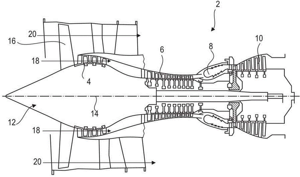
[0053] figure 1 A simplified form of an axial turbine engine is depicted. In this particular case, it's a twin-flow turbojet. The turbojet engine 2 comprises a first compression level called low-pressure compressor 4 , a second compression level called high-pressure compressor 6 , a combustion chamber 8 , and one or more turbine levels 10 . During operation, the mechanical power of the turbine 10 transmitted via the central shaft to the rotor 12 sets the two compressors 4 and 6 in operation. A gear reduction increases the rotational speed delivered to the compressor. Or each different turbine stage may be connected to the compressor stage via a concentric shaft. The compressor stage includes rows of rotor blades associated with rows of stator blades. Thus, the rotation of the rotor relative to its axi...


PUM

PropertyMeasurementUnit
lengthaaaaaaaaaa

Abstract

The present invention relates to an angle section of the blade rotor of a low-pressure compressor of an axial turbine engine compressor. The section comprises an arc external lantern ring (30) installed at the external housing of the turbine engine compressor in a concentric mode and an internal lantern ring. The section also comprises a row of rotor blades (42) extending in a radial direction and pitched in the lantern ring (30), and a blade box is form in such manner. The blades (42) of the box comprise the pitching legs (50) at the external end portion, wherein the pitching legs (50) are arranged in the thickness of the external lantern ring (30). The internal lantern ring comprises a pile used for pitching the blades (42).

Description

technical field [0001] The invention relates to a vane stator for an axial turbine engine. More specifically, the invention relates to an angular sector of an axial turbine engine stator forming a vane box. The invention likewise relates to a turbine engine provided with stator sectors according to the invention. Background technique [0002] The function of guiding the flow in an axial turbine engine is ensured by a stator part provided with blades. Specifically, the flow is turned in an axial compressor with the assistance of a guide vane assembly providing blades extending between concentric collars. Due to the blades, the outer collar is fixed to the outer casing and the inner collar is attached to the inner casing. [0003] In order to lighten the stator, it is known in the art that certain collars are realized in composite material. To simplify the stator assembly, the collar may be a half collar or may be a collar sector that extends over an angular segment of the...

Claims


Application Information

Patent Timeline
Patent Type & Authority Applications(China)
IPC IPC(8): F04D29/44F04D29/54
CPCF05D2260/36F05D2300/174F05D2300/6033F01D9/041F01D9/042Y02T50/60F05D2240/80
Inventor A.德克莱
Owner SAFRAN AERO BOOSTERS SA
Why Eureka
Try Eureka