A working hydraulic system of a loader that can recover overflow energy

A technology for hydraulic systems and loaders, which is applied in the directions of fluid pressure actuation system components, fluid pressure actuation devices, mechanical equipment, etc., can solve the problems of high cost of variable systems, inability to recycle overflow energy, etc. Effect

Inactive Publication Date: 2017-05-24
NORTH CHINA UNIV OF WATER RESOURCES & ELECTRIC POWER
View PDF5 Cites 0 Cited by
  • Summary
  • Abstract
  • Description
  • Claims
  • Application Information

AI Technical Summary

Problems solved by technology

At present, the main methods to reduce overflow loss include using a variable displacement pump to drive a hydraulic system or a dual-pump confluence hydraulic system, but the above two types of systems can only reduce overflow loss and cannot recycle overflow energy, and the cost of the variable displacement system is much higher quantitative system

Method used


Image

  • A working hydraulic system of a loader that can recover overflow energy
  • A working hydraulic system of a loader that can recover overflow energy
  • A working hydraulic system of a loader that can recover overflow energy

Examples


Embodiment Construction

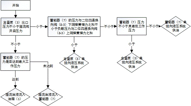
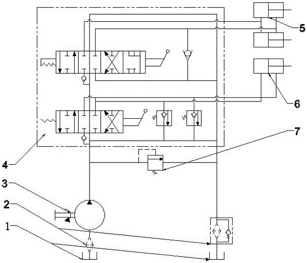
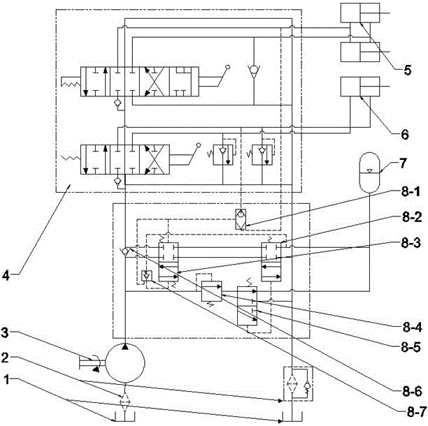
[0020] The specific embodiment of the present invention is as figure 2 with image 3 Shown in : the overflow valve (8-4) determines whether the outlet pressure of the quantitative pump (3) is not less than the opening pressure of the overflow valve (8-4), if not, then the two-position three-way reversing valve ( 8-5) Determine whether the accumulator (7) has reached the maximum working pressure. If it reaches the maximum working pressure, the overflow oil will flow back to the oil tank (1) through the lower position of the two-position three-way reversing valve (8-5). The oil flows into the accumulator (7) through the upper position of the two-position three-way reversing valve (8-5); on the other hand, if the outlet pressure of the quantitative pump (3) is lower than the opening pressure of the relief valve (8-4), The two-position four-way valve (8-3) determines whether the sum of the pressure of the accumulator (7) and the spring pressure at the lower end of the two-positi...


PUM


Abstract

The invention discloses a loader working hydraulic system capable of recycling overflow energy. Compared with a current hydraulic system, the loader working hydraulic system mainly has an energy accumulator and an overflow energy recycling valve additionallyarranged , wherein the overflow energy recycling valve consists of a load pressure acquiring valve, a switch valve, a two-position four-way valve, an overflow valve, a two-position three-way reversing valve, a one-way valve and a hydraulic-control one-way valve. The overflow energy recycling valve comprises a plurality of judging conditions, by which the hydraulic system disclosed by the invention can be guaranteed to safely recycle and reutilize overflow energy. The loader working hydraulic system has the beneficial effects of safely recycling the overflow energy of the working hydraulic system; and the whole system is hydraulically controlled, and no electrical control unit is introduced.

Description

technical field [0001] The patent of the present invention belongs to the technical field of construction machinery, and in particular relates to a working hydraulic system of a loader. Background technique [0002] The main operation mode of the loader is shoveling operation and loading operation. In order to complete these two types of operations, the hydraulic cylinder needs to be driven by the working hydraulic system to complete actions such as lifting, lowering, bucket collection, and unloading. [0003] figure 1 For the current general fixed-quantity pump-driven loader hydraulic system, its energy loss mainly includes overflow loss, throttling loss and neutral unloading loss. When the loader performs heavy-duty operations, the overflow loss is the main source of energy consumption in the working hydraulic system. At present, the main methods to reduce overflow loss include using a variable displacement pump to drive a hydraulic system or a dual-pump confluence hydra...

Claims


Application Information

Patent Timeline
Patent Type & Authority Patents(China)
IPC IPC(8): F15B11/16F15B1/02F15B21/14
Inventor 谭兆钧闫镇威原现杰
Owner NORTH CHINA UNIV OF WATER RESOURCES & ELECTRIC POWER
Why Eureka
Try Eureka