

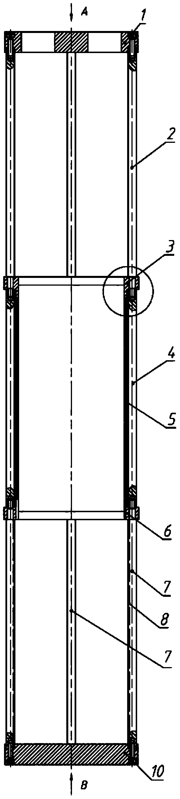
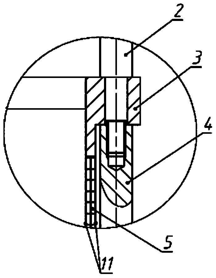
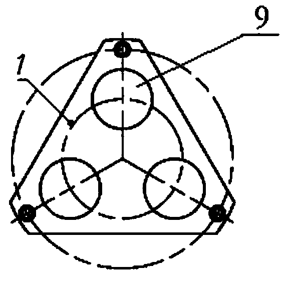
Long-stroke moving coil structure for electrodynamic shaker
An electric vibrating table, long-stroke technology, used in vibration testing, machine/structural component testing, impact testing, etc., can solve the problems of small contact area, low lateral stiffness, poor stability, etc., to avoid damage, guide good performance
- Summary
- Abstract
- Description
- Claims
- Application Information
AI Technical Summary
Problems solved by technology
Method used
Image

Examples
Embodiment Construction
[0033] In order to make the objectives, technical solutions and advantages of the present invention clearer, the technical solutions in the embodiments of the present invention will be described in more detail below in conjunction with the drawings in the embodiments of the present invention. In the drawings, the same or similar reference numerals denote the same or similar elements or elements having the same or similar functions throughout. The described embodiments are some, but not all, embodiments of the invention. The embodiments described below by referring to the figures are exemplary and are intended to explain the present invention and should not be construed as limiting the present invention. Based on the embodiments of the present invention, all other embodiments obtained by persons of ordinary skill in the art without making creative efforts belong to the protection scope of the present invention. Embodiments of the present invention will be described in detail b...
PUM
 Abstract
Description
Claims
Application Information