Temperature rise characteristic automatic detection device of low-tension current transformer

An automatic detection device, low-voltage current technology, applied in measuring devices, instruments, measuring electrical variables, etc., can solve the problems of long detection period, long detection period and low detection efficiency of low-voltage current transformers, so as to avoid errors and erroneous operations. Possibility, reduction of required time, high output current effect

Active Publication Date: 2016-02-03
CHINA ELECTRIC POWER RES INST +1
View PDF5 Cites 10 Cited by
  • Summary
  • Abstract
  • Description
  • Claims
  • Application Information

AI Technical Summary

Problems solved by technology

The detection of temperature rise characteristics is an important detection item for evaluating the performance of low-voltage current transformers, and it is also the most complicated and the longest detection period item in the detection process of all performance indicators of low-voltage current transformers
[0003] The existing temperature rise characteristic detection scheme is to increase the current through manual voltage regulation on the primary side of the low-voltage current transformer. The temperature of the low-voltage current transformer will increase with the increase of the primary side current, and its temperature rise High characteristics need to manually detect the environmental temperature change and the temperature change of the low-voltage current transformer under test, and judge whether it is stable. After the temperature rise is stable, remove the load on the secondary side of the low-voltage current transformer, and measure the secondary side of the low-voltage current transformer. Resistance, and then calculate the temperature rise value by deriving the resistance change. The detection cycle takes about 6-7 hours. The detection cycle is long, labor-intensive, and detection error is large. Only one low-voltage current transformer can be detected at a time, and the detection efficiency is low.

Method used


Image

  • Temperature rise characteristic automatic detection device of low-tension current transformer
  • Temperature rise characteristic automatic detection device of low-tension current transformer
  • Temperature rise characteristic automatic detection device of low-tension current transformer

Examples


Embodiment Construction

[0034] In order to better understand the present invention, the content of the present invention will be further described below in conjunction with the accompanying drawings and examples.

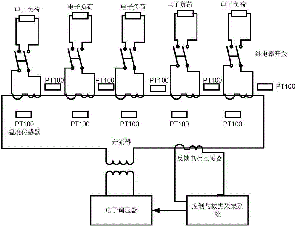
[0035] The automatic detection device for the temperature rise characteristic of the low-voltage current transformer provided by the present invention is as follows: Figure 1-5 As shown, the device includes a control and data acquisition system, a current generating device, a low-voltage current transformer, a switch, an electronic load and a temperature sensor; the control and data acquisition system are bidirectionally connected with the current generating device, and the current generating The output terminal of the device is connected in series with the input terminal of the low-voltage current transformer, the output terminal of the low-voltage current transformer is connected in parallel with the electronic load through a switch, and the temperature sensor is fixed on the low-voltage...


PUM


Abstract

The present invention provides a temperature rise characteristic automatic detection device of a low-tension current transformer. The temperature rise characteristic automatic detection device comprises a control and data acquisition system, a current generation device, a low-tension current transformer, a switch, an electronic load and a temperature sensor. The control and data acquisition system is in bidirectional connection with the current generation device; the output end of the current generation device is connected in series with the input end of the low-tension current transformer; the output end of the low-tension current transformer is connected in parallel with the electronic load through the switch; and the temperature sensor is fixed on the low-tension current transformer. The detection device provided by the invention may complete characteristic automatic detection of a plurality of current transformers at once without personnel participation in the whole process, and therefore the detection efficiency is greatly improved.

Description

technical field [0001] The invention relates to a detection device, in particular to an automatic detection device for the temperature rise characteristic of a low-voltage current transformer. Background technique [0002] Low-voltage current transformers for metering are the main measuring instruments for power marketing, and their performance indicators are directly related to the accuracy of charging. The detection of temperature rise characteristics is an important test item for assessing the performance of low-voltage current transformers, and it is also the most complicated and the longest test item in the process of testing all performance indicators of low-voltage current transformers. [0003] The existing temperature rise characteristic detection scheme is to increase the current through manual voltage regulation on the primary side of the low-voltage current transformer. The temperature of the low-voltage current transformer will increase with the increase of the ...

Claims


Application Information

Patent Timeline
Patent Type & Authority Applications(China)
IPC IPC(8): G01R35/02
Inventor 陈习文雷民张军王斯琪卢冰付济良周玮刘方明汪泉齐聪郭子娟匡义朱赤丹余雪芹黄莹
Owner CHINA ELECTRIC POWER RES INST
Why Eureka
Try Eureka