Scanning type beam detection device and method

A detection device and a scanning technology, which is applied in the field of safety precautions and railway safety detection, can solve the problems of increasing technical complexity, restricting popularization and application, increasing wiring harness equipment, etc., achieving simplification of anti-interference technology, reducing equipment volume, The effect of structural optimization

Active Publication Date: 2016-02-03
王启华
View PDF6 Cites 6 Cited by
  • Summary
  • Abstract
  • Description
  • Claims
  • Application Information

AI Technical Summary

Problems solved by technology

In order to ensure wide coverage and minimize missed detection, it is necessary to greatly increase the number of wiring harness devices, which w...

Method used


Image

  • Scanning type beam detection device and method
  • Scanning type beam detection device and method
  • Scanning type beam detection device and method

Examples


Embodiment 1

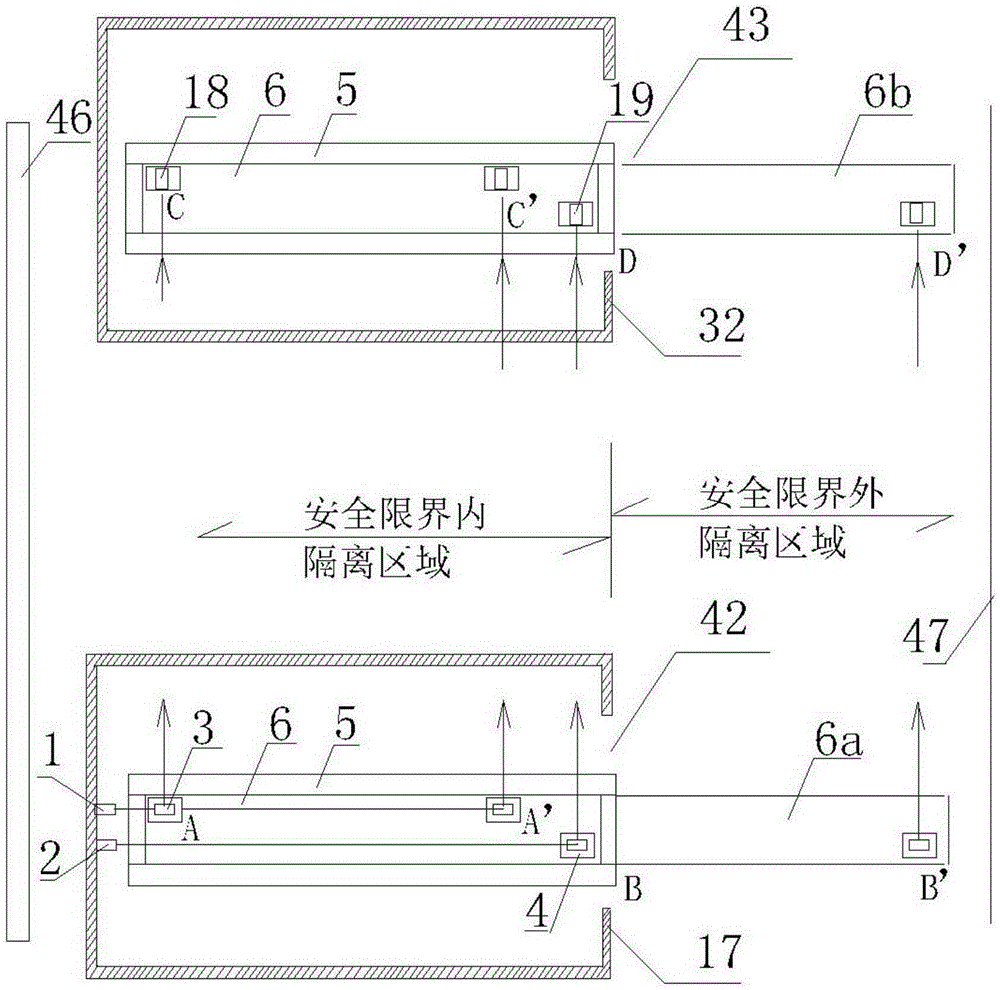
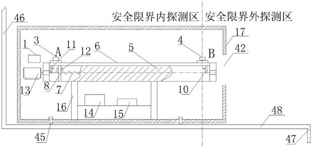
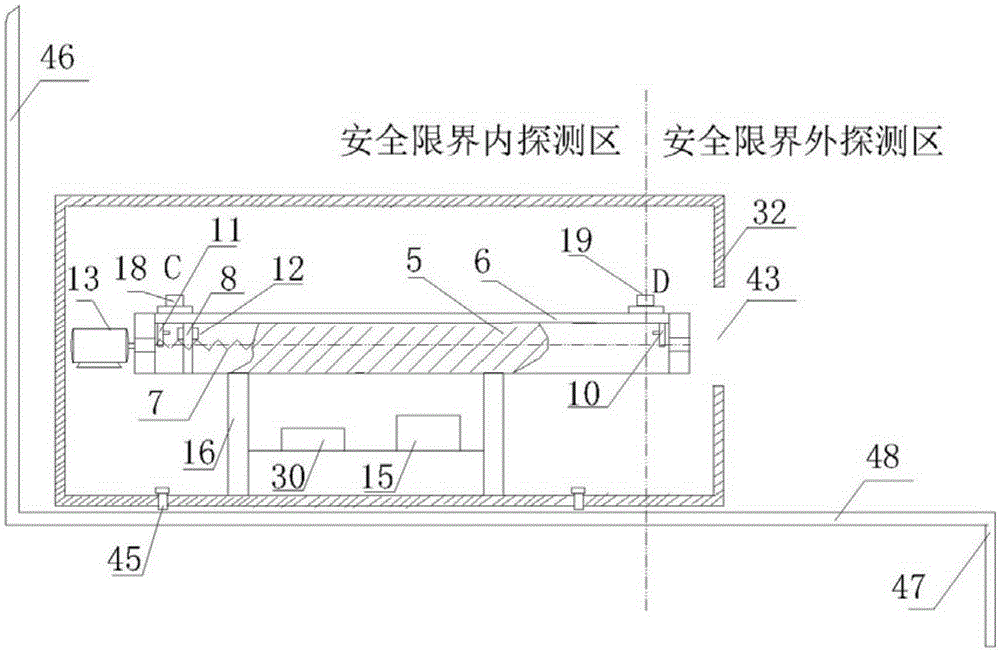
[0054] Such as Figure 1-3 As shown, a scanning beam detection device provided in this embodiment includes two scanning brackets 6, an inner beam emitter 1, an outer beam emitter 2, an inner beam refractor 3, an outer beam Beam refractor 4, inner zone beam receiver 18 and outer zone beam receiver 19;

[0055] The scanning support 6 is slidably arranged in the isolated area within the safety limit on the platform 48 .

[0056] The two scanning supports 6 are divided into a transmitting scanning frame 6a and a receiving scanning frame 6b; an isolation area is formed between the safety door 46 and the edge 47 of the platform 48, and the isolation area is divided into an isolation area within the safety limit and a safety limit according to the set safety limit Outer isolation area. The two scanning brackets 6a and 6b are respectively arranged in parallel in the isolated areas within the safety limits corresponding to the front and rear of the vehicle.

[0057] The emission sca...

Embodiment 2

[0072] A method for detecting a platform isolation area by using the above-mentioned scanning beam detection device, comprising the following steps:

[0073] Step 1, after the controller 15 receives the closing and locking signal of the safety door 46 of the platform, the controller 15 starts the beam emitter 1 in the inner zone and the beam transmitter 2 in the outer zone through the beam emitting circuit board 14; the controller 15 starts the beam emitter The receiving circuit board 30 works with the beam receiver 18 in the linkage inner zone and the beam receiver 19 in the outer zone;

[0074] Step 2, the controller 15 drives the transmitting scanning frame 6a and the receiving scanning frame 6b to move synchronously through the screw drive mechanism, and the front ends of the transmitting scanning frame 6a and the receiving scanning frame 6b extend into the isolation area outside the safety limit;

[0075] The inner beam emitted by the inner beam transmitter 1 is refracted...


PUM


Abstract

The invention relates to a scanning type beam detection device, comprising a beam emitter, a beam receiver and two scanning supports; the scanning supports are arranged on the head and the part ends of an isolation area in parallel and sliding manners; two scanning supports are an emission scanning support and a reception scanning support; the reception scanning support is provided with the beam receiver; the emission scanning support is provided with the beam emitter and the beam refractor; the emission scanning support and the reception scanning support synchronously slide; the beam emitted by the beam emitter is directly irradiated into the beam receiver or is irradiated into the beam receiver after being refracted by the beam reflector; and the beam sweeps across the whole isolation zone for detection. The invention realizes the detection area whole coverage of the isolation area inside and outside the safety boundary of the high speed rail and the urban train, realizes seamless high density detection, and enables the structure to be more reasonable and the cost to be lower. The invention has a safer, effective and reliable protection function, and, in the meantime, is applied in the wide and long isolation channels in other airports, harbors and nuclear plants.

Description

technical field [0001] The invention relates to the technical field of safety protection and railway safety detection, in particular to a scanning beam detection device and method for high-speed railway and urban railway platforms. Background technique [0002] There is a safety door (or screen door) device on the platform of high-speed railway and intercity railway. The safety door (or screen door) is similar to the safety door (or screen door) device of the subway, which can prevent passengers from falling off the track while waiting for the train, and the train The danger caused by negative air pressure when passing at high speed can reduce parking delays and driving accidents caused by human beings. However, in order to ensure the safe operation of the train, an isolated area of ​​certain width must be reserved between the train and the safety door (or screen door), and this area is also an emergency passage for passengers when the train stops. [0003] Generally speaki...

Claims


Application Information

Patent Timeline
IPC IPC(8): G01V8/20
Inventor 王启华
Owner 王启华
Why Eureka
Try Eureka