Output method and device of pulse laser

A pulsed laser and pulsed signal technology, applied in the laser field, can solve problems affecting laser pulse performance, different magnification factors, etc.

Active Publication Date: 2016-02-03
MAXPHOTONICS CORP
View PDF5 Cites 0 Cited by
  • Summary
  • Abstract
  • Description
  • Claims
  • Application Information

AI Technical Summary

Problems solved by technology

like image 3 Shown is a schematic diagram of the laser output energy of the laser using signal light with a fixed period, where the abscissa represents time, and the ordinate represents the amplification factor of the pulse signal by the gain medium. Due to the different number of inversion particles generated in the signal light cycle, in Before the inversion particles generated per unit time reach a steady state, the amplification factor of the pulse signal by the gain medium is different, which affects the performance of the output laser pulse

Method used


Image

  • Output method and device of pulse laser
  • Output method and device of pulse laser
  • Output method and device of pulse laser

Examples


Embodiment Construction

[0053] In order to make the above objects, features and advantages of the present application more obvious and comprehensible, the present application will be further described in detail below in conjunction with the accompanying drawings and specific implementation methods.

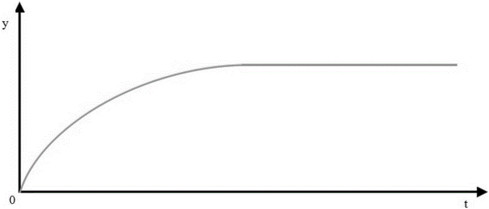
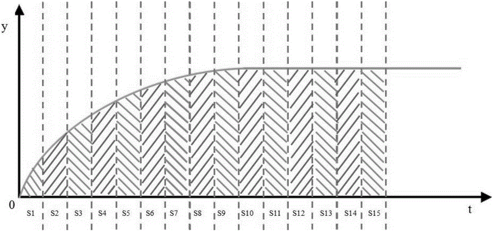
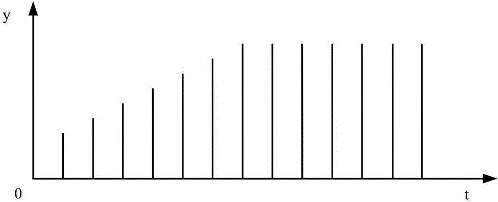
[0054] One of the core concepts of the embodiment of the present application is to adjust the input timing of the pulse signal in the non-steady state through the sampling inversion particle number obtained through the experiment in advance, so that in the non-steady state and the steady state, each signal light interval Generates the same number of inverted particles.

[0055] refer to Figure 4 , which shows a flow chart of the steps of an embodiment of a pulsed laser output method of the present application, which may specifically include the following steps:

[0056] Step 101, using the preset number of sampling inversion particles to generate an unsteady pulse signal; the number of sampling inversi...


PUM


Abstract

The invention provides an output method of a pulse laser. The method comprises that a preset sampling counter-rotating particle population is used to generated unstable-state pulse signals; the amount of counter particles in the counter particle accumulation process of a gain medium of the pulse laser under different pumping powers is sampled to obtain the counter-rotating particle population; unstable-state pulse signals and preset stable pulse signals are combined to obtain input pulse signals; and when the pulse laser is started, the input pulses signals are used for control output of the pulse laser. When the gain medium is in the unstable state, the input sequence of the pulse signals is adjusted to ensure that counter-rotating particle population in each signal light interval in the unstable and stable states is the same, and further to ensure that the amplification multiple for each input signal light by the gain medium is the same.

Description

technical field [0001] The present application relates to the field of laser technology, in particular to a pulse laser output method and a pulse laser output device. Background technique [0002] The gain medium in the pulsed laser realizes the accumulation of the inversion particle number by absorbing the pump light, and the inversion particle number amplifies the input pulse signal to realize the output of the pulsed laser. like figure 1 Shown is a schematic diagram of the accumulation process of the number of reversed particles of the gain medium, where the abscissa is time, and the vertical axis is the number of reversed particles generated per unit time. After the gain medium absorbs the pump light, the number of inversion particles increases gradually until reaching a steady state, and the number of inversion particles generated per unit time reaches the maximum. [0003] like figure 2 Shown is a schematic diagram of the gain medium amplifying the signal light wit...

Claims


Application Information

Patent Timeline
Patent Type & Authority Applications(China)
IPC IPC(8): H01S3/10H01S3/09
Inventor 居剑李连城刘一然张盼盼李全法蒋峰
Owner MAXPHOTONICS CORP
Why Eureka
Try Eureka