
Experiment system and method for unified electric energy quality controller

A power quality and experimental system technology, applied in electrical components, circuit devices, AC network circuits, etc., can solve problems such as instability, grid voltage fluctuations, and shortages, and achieve high voltage regulation accuracy, easy operation and simple structure and principle. Effect

Inactive Publication Date: 2016-02-03
ZHUZHOU NAT ENG RES CENT OF CONVERTERS
View PDF3 Cites 6 Cited by
  • Summary
  • Abstract
  • Description
  • Claims
  • Application Information

AI Technical Summary

Problems solved by technology

[0003] At present, the following problems exist in the experimental verification of UPQC functions: 1) There is a lack of experimental platform experimental verification for high-voltage and large-capacity UPQC, and because UPQC has many functions, a single functional experimental circuit can no longer meet the experimental requirements of this variety of functions; 2) When verifying the dynamic voltage compensation function, the voltage fluctuation of the grid is generally simulated by a voltage regulator, whose voltage regulation accuracy is low, and can only realize the change of the voltage amplitude; when testing the reactive power compensation function, it is usually directly injected into the grid A certain amount of reactive power is likely to cause fluctuations and instability to the grid voltage

Method used


Image

  • Experiment system and method for unified electric energy quality controller
  • Experiment system and method for unified electric energy quality controller
  • Experiment system and method for unified electric energy quality controller

Examples


Embodiment Construction

[0023] The present invention will be further described below in conjunction with the accompanying drawings and specific preferred embodiments, but the protection scope of the present invention is not limited thereby.

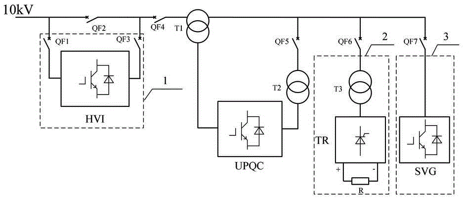
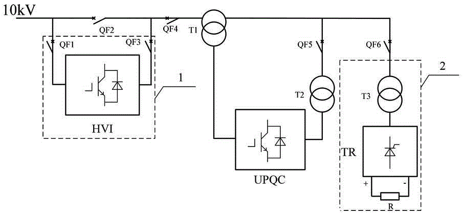
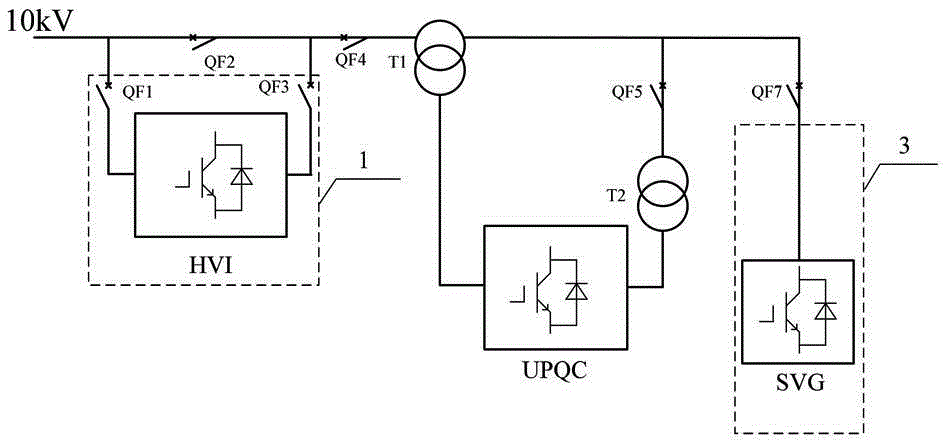
[0024] Such as figure 1 As shown, the experimental system of the unified power quality controller in this embodiment includes a controllable voltage generating unit 1 for generating a dynamically adjustable voltage to simulate grid voltage changes, for generating current harmonics and providing harmonics for nonlinear loads Load unit 2, reactive power test unit 3 for generating reactive power, bypass circuit breaker QF2, first circuit breaker QF6, second circuit breaker QF7, after the controllable voltage generating unit 1 and bypass circuit breaker QF2 are connected in parallel One end is connected to the grid voltage (specifically 10kV grid voltage in this embodiment), and the other end is connected to the series side of the unified power quality controller (U...


PUM


Abstract

The invention discloses an experiment system and method for a unified electric energy quality controller. The system includes a controllable voltage generating unit for generating dynamically adjustable voltage, a harmonic load unit used for generating current harmonic and providing a nonlinear load, a reactive power test accompanying unit use for generating reactive power, a bypass circuit breaker, a first circuit breaker and a second circuit breaker; one end of the controllable voltage generating unit is connected in parallel with the bypass circuit breaker, and thereafter is connected into power grid voltage, and the other end of the controllable voltage generating unit is connected with the series side of a UPQC; the harmonic load unit is connected with the parallel side of the UPQC through the first circuit breaker; and the reactive power test accompanying unit is connected with the parallel side of the UPQC through the second circuit breaker. According to the method, the above system is utilized to realize voltage compensation and harmonic suppression experiments and reactive power compensation experiments. With the method adopted, various kinds of function experimental confirmation of the unified electric energy quality controller can be realized based on one such experiment system. The experiment system and method have the advantages of simple structure principles, easy and convenient operation and excellent experimental performance.

Description

technical field [0001] The invention relates to a unified power quality controller, in particular to an experimental system and method for a unified power quality controller. Background technique [0002] The current growing demand for electricity has brought new challenges to the power supply of the grid. On the one hand, the nonlinear loads used in industrial production generate a large number of harmonic currents and reactive currents; on the other hand, with the high-tech industry With the rise of the power grid, the application of sensitive equipment such as high-performance office equipment, precision experimental instruments, and precision control equipment in the power grid is increasing year by year. These devices require the power grid to provide stable, uninterrupted, reliable and high-quality power supply. Unified power quality controller (UnifiedPowerQualityConditioner, UPQC), as a comprehensive power quality control device, has two parallel and series inverters...

Claims


Application Information

Patent Timeline
IPC IPC(8): H02J3/00H02J3/01H02J3/18H02J3/24
CPCY02E40/30Y02E40/40
Inventor 邓明黄燕艳吴强周方圆刘华东罗仁俊吴选保龚芬吴明水张典王才孝胡前邱文俊吕顺凯朱建波龙礼兰涂绍平文韬
Owner ZHUZHOU NAT ENG RES CENT OF CONVERTERS
Learn More