Motor frame and disc type motor adopting same

A motor skeleton, skeleton technology, applied in the shape/style/structure of winding insulation, magnetic circuit shape/style/structure, magnetic circuit static parts, etc. Complex operation process and other problems, to achieve the effect of saving materials, saving maintenance, and simplifying the process

Active Publication Date: 2016-02-03
CHANGZHOU FULLINGMOTOR
View PDF11 Cites 0 Cited by
  • Summary
  • Abstract
  • Description
  • Claims
  • Application Information

AI Technical Summary

Problems solved by technology

[0002] The iron core assembly of the disc motor is generally composed of a plurality of iron cores distributed along the circumferential direction, and the accuracy of the angle between adjacent iron cores is relatively high. After the housing is positioned, it is fixed with glue. The coil inside the iron core n

Method used


Image

  • Motor frame and disc type motor adopting same
  • Motor frame and disc type motor adopting same
  • Motor frame and disc type motor adopting same

Examples


Embodiment 1

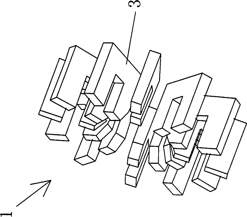
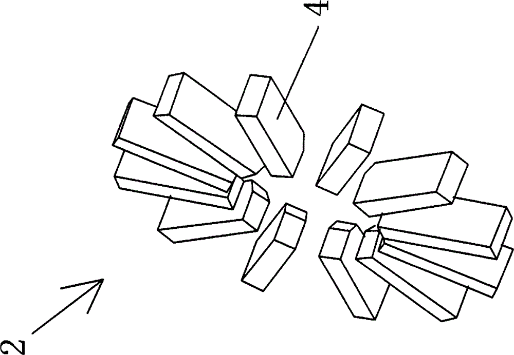
[0040] Such as figure 1 and figure 2 , the disc motor core assembly includes: a stator core assembly 1 and an end cover core assembly 2, the stator core assembly 1 is formed by a plurality of U-shaped stator cores 3 arranged in the circumferential direction, adjacent The included angle between the stator cores 3 is set to a constant value according to the type of the motor, and the end cover core assembly 2 is formed by a plurality of block-shaped end cover cores 4 arranged along the circumferential direction.

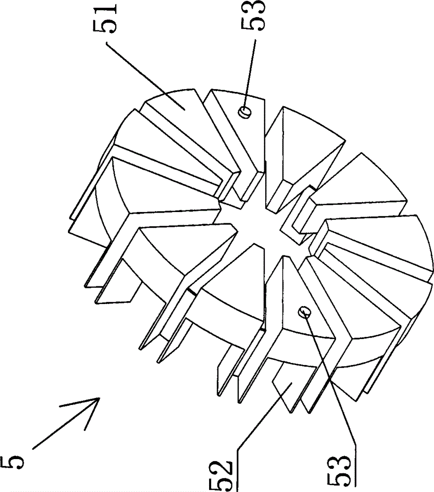
[0041] Such as image 3 and Figure 4, the stator core frame 5 includes a plurality of sector blocks 51 arranged along the circumferential direction, the angle between the sector blocks 51 is a constant value, and the outer edge of the adjacent sector blocks 51 is provided for connecting the adjacent sector blocks The groove piece 52, the section of this groove piece 52 is U-shaped, and the shape of the groove in the groove piece 52 matches the gap between the adja...

Embodiment 2

[0045] The above-mentioned stator core skeleton and end cover iron core skeleton are adopted in the disc motor in this embodiment, which includes: end cover 8 and casing 9, such as Figure 9-11 , the end cap 8 includes a ring body 81, one side of the ring body 81 is provided with a circular cover plate 82, the center of the cover plate 82 is provided with a circular step 83, and the center of the step 83 is provided with a circular through hole 84 , A pair of end cover positioning blind holes 85 are symmetrically arranged on the inner surface of the cover plate 82 .

[0046] Such as Figure 12-14 , the casing 9 includes a cylindrical body 91 with an annular cross section, a circular partition 92 is provided at the middle section of the cylindrical body 91, and the partition plate 92 divides the inner cavity of the cylindrical body 91 into two, and the partition plate The center of 92 is provided with the cylindrical bearing 93 that extends to both sides, and the center of thi...


PUM


Abstract

The invention relates to a motor frame and a disc type motor adopting the motor frame. The motor frame comprises a stator iron core frame and an end cover iron core frame. The stator iron core frame comprises a plurality of fan-shaped blocks which are circumferentially arranged; the edges of the outer ends of the fan-shaped blocks are provided with groove sheets used for connecting adjacent fan-shaped blocks; grooves in the groove sheets are shaped to match gaps between the adjacent fan-shaped blocks; a plurality of stator iron cores are suitable for being mounted in the stator iron core frame, so that a stator iron core assembly can be formed; the end cover iron core frame comprises a plurality of fan-shaped sheets which are arranged circumferentially; the inner ends of the fan-shaped sheets are connected with each other so as to form one body; and a plurality of end cover iron cores are suitable for being mounted in gaps between adjacent fan-shaped sheets, so that an end cover iron core assembly can be formed. Compared with a mode in which fixation is realized through glue, the motor frame can ensure constant invariability of included angles between the stator iron cores and between the end cover iron cores.

Description

technical field [0001] The invention relates to a motor skeleton and a disc motor adopting the motor skeleton, which can keep the position of the iron core of the motor fixed. Background technique [0002] The iron core assembly of the disc motor is generally composed of a plurality of iron cores distributed along the circumferential direction, and the accuracy of the angle between adjacent iron cores is relatively high. After the housing is positioned, it is fixed with glue. The coil inside the iron core needs to be wound and shaped and covered with insulating tape on the outside. The process is complicated. At the same time, the heat emitted by the motor will heat the glue and heat The glue is easy to age and soften, which will change the angle between the iron cores and affect the normal operation of the motor. Contents of the invention [0003] The technical problem to be solved by the present invention is to provide a motor frame capable of supporting the iron cores ...

Claims


Application Information

Patent Timeline
IPC IPC(8): H02K1/12H02K1/18H02K3/34
Inventor 崔文剑
Owner CHANGZHOU FULLINGMOTOR
Why Eureka
Try Eureka