
Maximum output power configuration with ue preference in carrier aggregation

A technology of maximum output power and maximum transmission power, applied in the field of maximum output power configuration, which can solve the problems of large path loss and small coverage.

Active Publication Date: 2016-02-03
HFI INNOVATION INC
View PDF6 Cites 2 Cited by
  • Summary
  • Abstract
  • Description
  • Claims
  • Application Information

AI Technical Summary

Problems solved by technology

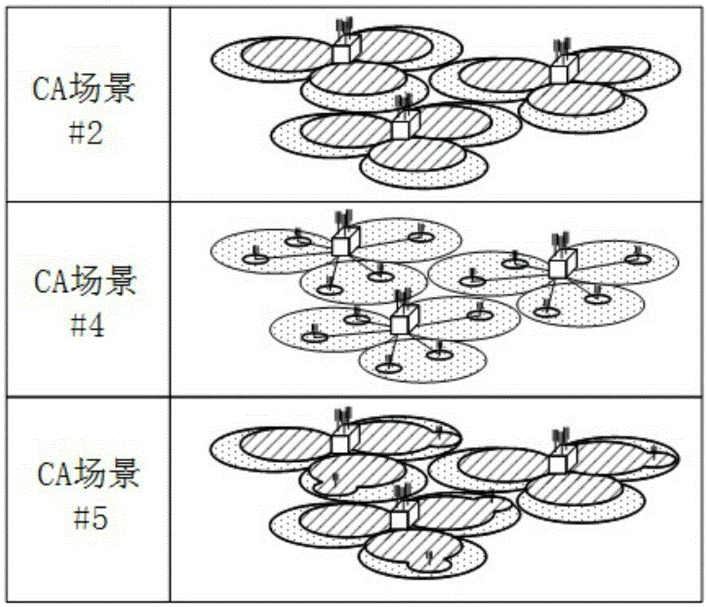
The F1 cell and the F2 cell coexist (co-located) and overlap (overlaid), but because the path loss of F2 is larger than that of F1, the coverage of F2 is smaller than that of F1.

Method used


Image

  • Maximum output power configuration with ue preference in carrier aggregation
  • Maximum output power configuration with ue preference in carrier aggregation
  • Maximum output power configuration with ue preference in carrier aggregation

Examples


Embodiment Construction

[0026] DETAILED REFERENCES In some embodiments of the invention, examples of which are illustrated in the accompanying drawings.

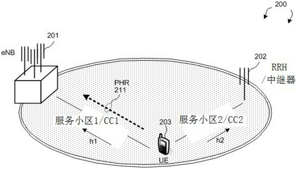
[0027] figure 2It is a schematic diagram of a wireless communication system 200 provided by the present invention to illustrate the maximum output power control configured by the user equipment. The wireless communication system 200 includes a base station eNB201 , a remote radio head (remote radio head, RRH) or a repeater 202 , and a user equipment UE203 . Using carrier aggregation (carrier aggregation, CA), UE203 configures multiple component carriers (component carriers, CCs) and multiple serving cells (serving cells) to provide services to UE203. For example, UE203 is served by eNB201 and RRH202, wherein eNB201 is located in serving cell 1 of CC1, and RRH202 is located in serving cell 2 of CC2. In carrier aggregation CA, different component carriers (CCs) have different channel characteristics, especially when the different component carrier...


PUM


Abstract

A method of maximum output power configuration with UE preference in carrier aggregation is provided.A UE configures multiple component carriers(CCs)with carrier aggregation for communicating with a serving base station in a mobile communication network. The UE determines channel condition of multiple serving cells over the corresponding multiple CCs. The UE then determines maximum output power for each CC based at least in part on the corresponding channel condition of each CC. Finally,the UE transmits power headroom report(PHR)for each CC to the serving base station,wherein the PHR is calculated based on the determined maximum output power.As a result,the reported PH information is channel condition dependent,which can be used by eNB for facilitating better transmission scheduling.

Description

[0001] Cross References to Related Applications [0002] Claims to the Claims of this Application Pursuant to 35 U.S.C. §119 priority is claimed to the following application: U.S. Provisional Application No. 61 / 816,264, filed April 26, 2013, entitled "Method of UEPmaxConfiguration for Carrier Aggregation System," which application is hereby incorporated by reference The subject of the application. technical field [0003] The present invention generally relates to wireless network communications, and more particularly, to user equipment preferred maximum output power configuration in carrier aggregation. Background technique [0004] A Long-Term Evolution (Long-Term Evolution, LTE) system has the advantages of high peak data rate, low delay, large system capacity and low operation cost due to its simple network architecture. At the same time, the LTE system also provides seamless integration for older wireless networks, such as Global System for Mobile Communication (GSM),...

Claims


Application Information

Patent Timeline
IPC IPC(8): H04W52/04
CPCH04W52/365H04B17/336H04L5/00H04L5/001H04W52/146H04W52/241H04W52/34H04W52/367H04W72/02
Inventor 游家豪陈儒雅陈义昇李彦伯韦宜君沈仓亿
Owner HFI INNOVATION INC
Learn More