
Dragging type middle-sized disc harrow

A disc harrow, drag-type technology, applied in the direction of harrow, application, agriculture, etc., can solve the problems of low adjustment efficiency, complex structure, high work intensity, etc., and achieve the effect of prolonging the service life, convenient and quick operation, and high efficiency.

Active Publication Date: 2016-02-10
YUCHENG YIJIA MACHINERY
View PDF6 Cites 2 Cited by
  • Summary
  • Abstract
  • Description
  • Claims
  • Application Information

AI Technical Summary

Problems solved by technology

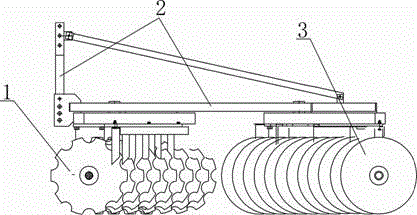
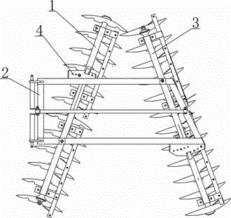
The current medium-sized disc harrow structure such as figure 1 , 2 As shown, it usually includes the front rake group 1 and the rear rake group 3, both of which are connected to the suspension rake frame 2 through the pressure plate and standard parts. Loosen the bolts of the pressure plate respectively, manually move the front rake group and the rear rake group, and adjust the closing position of the angle adjustment plate 4, the operation is troublesome, the work intensity is high, and the adjustment efficiency is low
In addition, the existing medium-sized disc harrows are all in the form of suspension, that is, they are connected to the tractor through their own three-point suspension. During the work of the suspended mid-sized disc harrow, due to the high-lying and uneven ground, the entire harrow body will generate lateral force with the swing of the tractor, which greatly Increases the axial load on the blades, thereby reducing the working life of the blades and the entire disc harrow

Method used


Image

  • Dragging type middle-sized disc harrow
  • Dragging type middle-sized disc harrow
  • Dragging type middle-sized disc harrow

Examples


Embodiment Construction

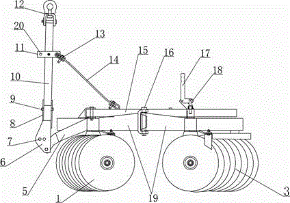
[0014] see figure 2 , 3 As shown, the present invention discloses a drag-type medium-sized disc harrow, which includes a front rake group 1 and a rear rake group 3 composed of a main shaft, rake blades, intermediate tubes, bearing assemblies and beams, both of which are fixed at the same end There is an articulated arm 10 extending to the middle, and the top ends of the two articulated arms 10 are hinged by a rotating shaft 16. The above structure ensures that the front rake group 1 and the rear rake group 3 can rotate relative to each other, and then the deflection angle between them can be adjusted; the front rake group 1 and the rear rake group 3 is further provided with a longitudinal beam 15, the front end of the longitudinal beam 15 is hingedly connected with the front rake group 1, and the middle and rear part of the longitudinal beam 15 is provided with several vertical The positioning hole 21 of the rear rake group 3 is provided with an adjusting pin 18 that coopera...


PUM


Abstract

The invention discloses a dragging type middle-sized disc harrow. The dragging type middle-sized disc harrow comprises a front harrow set and a rear harrow set, wherein hinging arms extending to the middle are fixed to the same ends of the front harrow set and the rear harrow set, the top ends of the two hinging arms are hinged through a rotary shaft, a longitudinal beam is arranged between the front harrow set and the rear harrow set, the front end of the longitudinal beam is hinged to the front harrow set, a plurality of positioning holes are formed in the rear middle portion of the longitudinal beam, and an adjusting pin is arranged on the rear harrow set; two connecting plates are arranged on the front side of the front harrow set in a relatively fixed mode, and the two connecting plates are hinged to a traction assembly located in front of the connecting plates. Due to the fact that the front harrow set and the rear harrow set are hinged together, deflection adjustment is convenient and quick, time and labor are saved, and efficiency is extremely high. In work, a tractor is in one-point dragging connection with a harrow body, the influence of swinging of the tractor on a harrow disc and the harrow body is reduced, and then the service life of a whole set of equipment can be prolonged; when the disc harrow is transported in an idle state, the whole device is fixed to the tail of the tractor safely and firmly through a three-point suspension mechanism formed by a suspension hole and two suspension pins.

Description

technical field [0001] The invention relates to an agricultural machine, in particular to a medium-sized disc harrow of an agricultural land preparation machine. Background technique [0002] As an agricultural soil preparation machine, the medium-sized disc harrow is widely used in crushing soil after plowing, soil preparation before sowing, mixing soil and fertilizer, and stubble removal in light and medium soil. mechanical. The current medium-sized disc harrow structure such as figure 1 , 2 As shown, it usually includes the front rake group 1 and the rear rake group 3, both of which are connected to the suspension rake frame 2 through the pressure plate and standard parts. Respectively loosen the pressure plate bolts, artificially move the front rake group and the rear rake group, and adjust the closing position of the angle adjustment plate 4, the operation is relatively troublesome, the work intensity is relatively large, and the adjustment efficiency is low. In add...

Claims


Application Information

Patent Timeline
IPC IPC(8): A01B21/08A01B23/04
Inventor 秦吉强王成
Owner YUCHENG YIJIA MACHINERY
Learn More