Filter device and dust removal equipment

A filter device and filter technology, applied in the direction of combined devices, dispersed particle separation, chemical instruments and methods, etc., can solve the problems of reducing dust removal efficiency, increasing the noise of dust removal equipment, and affecting the service life of filter 1, so as to ensure dust removal Efficiency and the effect of prolonging the service life

Active Publication Date: 2016-02-10
胡国海
View PDF4 Cites 3 Cited by
  • Summary
  • Abstract
  • Description
  • Claims
  • Application Information

AI Technical Summary

Problems solved by technology

[0005] However, as the dust increases, the dust collected in the dust collection chamber 2 is easily affected by the power motor, and tends to move to the filter 1, so that the dust adheres to the filter 1 and blocks the filter 1. filter screen
This will not only increa

Method used


Image

  • Filter device and dust removal equipment
  • Filter device and dust removal equipment
  • Filter device and dust removal equipment

Examples


Embodiment Construction

[0034] The core of the present invention is to provide a filtering device, which can keep dust away from the filter and prolong the service life of the filter during the working process. Another core of the present invention is to provide a dust removal device with the above filter device.

[0035] In order to enable those skilled in the art to better understand the solution of the present invention, the present invention will be further described in detail below in conjunction with the accompanying drawings and specific embodiments.

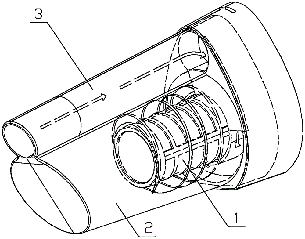
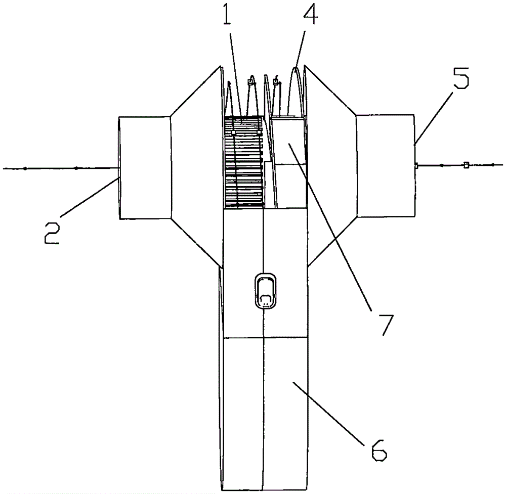
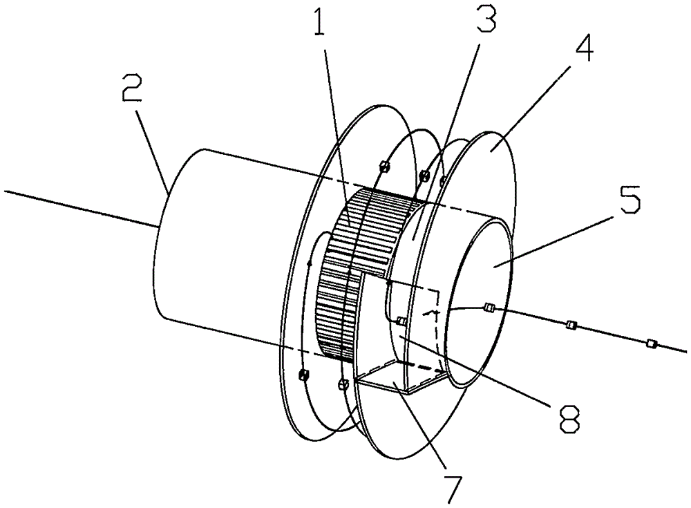
[0036] Please refer to Figure 2 to Figure 5 , figure 2 It is a structural schematic diagram of the first specific embodiment of the filtering device provided by the present invention, image 3 for figure 2 The schematic diagram of the local structure of the filter device shown, Figure 4 for figure 2 Schematic diagram of the airflow trajectory of the filter device shown, Figure 5 for figure 2 Side view of the filtration device shown...


PUM


Abstract

The invention discloses a filter device. The filter device comprises a working chamber and a filter arranged inside the working chamber, wherein one end of the filter is connected with an air outlet channel and a connecting shaft is coaxially installed at the other end of the filter; a spiral plate surrounds at least 90% of one circle of the connecting shaft so as to form a spiral air duct; an air inlet channel communicated with the spiral air duct is arranged in the connecting shaft; and the side of the working chamber is communicated with a dust chamber. Compared with the prior art, the filter device has the advantages that the side of the working chamber of the filter device is communicated with the dust chamber; gas enters the working chamber along the spiral air duct and then spirally moves; and the dust approaches the side wall of the working chamber under the action of the centrifugal force and moves along the side wall, and in the process, the dust can enter the dust chamber from the side of the working chamber to keep away from the filter, thus prolonging the service life of the filter and ensuring the dust removal efficiency. The invention also discloses dust removal equipment.

Description

technical field [0001] The invention relates to the technical field of dust removal, in particular to a filtering device. The present invention also relates to a dust removal device provided with the above filter device. Background technique [0002] With the rapid development of economic construction, the requirements for the environment are getting higher and higher, and various filter devices have emerged as the times require. Filter devices generally use motors to rotate at high speed to generate negative air pressure in the sealed housing to absorb dust. To achieve the purpose of dust removal. [0003] Please refer to figure 1 , figure 1 It is a structural schematic diagram of a typical filter device, wherein the direction indicated by the arrow in the figure is the movement direction of the dust when the vacuum cleaner is working. [0004] From figure 1 As can be seen from the direction indicated by the arrow in the middle, in the dust removal equipment of the pri...

Claims


Application Information

Patent Timeline
IPC IPC(8): B01D50/00
Inventor 胡国海
Owner 胡国海
Why Eureka
Try Eureka