A working method of a pipe mold powder spraying machine

A working method and technology of tube mold powder, applied in the working field of tube mold powder spraying machine, can solve the problems of increasing production cost, short service life of screw rod, high maintenance cost, etc., to improve production efficiency, reduce mechanical transmission, and reduce cost effect

Active Publication Date: 2017-12-22
WUHU XINXING DUCTILE IRON PIPES
View PDF6 Cites 0 Cited by
  • Summary
  • Abstract
  • Description
  • Claims
  • Application Information

AI Technical Summary

Problems solved by technology

The screw rod of this device is relatively short, so it is not easy to be stuck. However, during the wind blowing process, when the resistance in the 6m pipe is large, the wind will blow back to the position of the large hopper and the bearing seat, causing the bearing to be damaged and unable to add pipe mold powder, resulting in shutdown for maintenance. As a result, continuous production is stopped; the failure rate of its mechanical transmission is high, and the screw rod, bearing, and conveying pipe are worn out quickly, which increases the maintenance workload and increases the production cost.
[0005] According to the above two pipe mold powder conveying devices, in actual production, due to the mutual friction between the screw rod and the pipe mold powder, the service life of the screw rod is short, and the processing cost of the screw rod is high.
Another type of conveying device also has problems, such as the frequent occurrence of air return, which affects continuous production, high failure rate, high maintenance cost, and has a great impact on product quality

Method used


Image

  • A working method of a pipe mold powder spraying machine
  • A working method of a pipe mold powder spraying machine

Examples


Embodiment Construction

[0033] The specific implementation of the present invention will be described in further detail below by describing the embodiments with reference to the accompanying drawings, so as to help those skilled in the art have a more complete, accurate and in-depth understanding of the inventive concepts and technical solutions of the present invention.

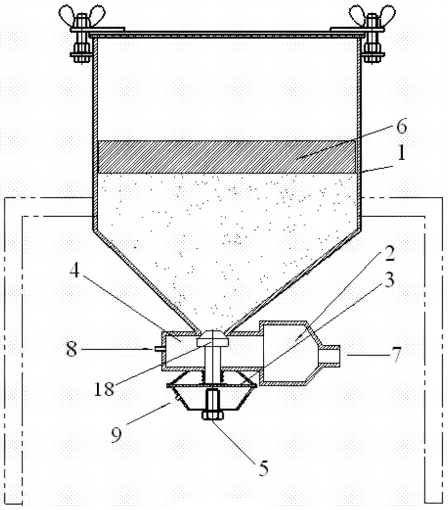
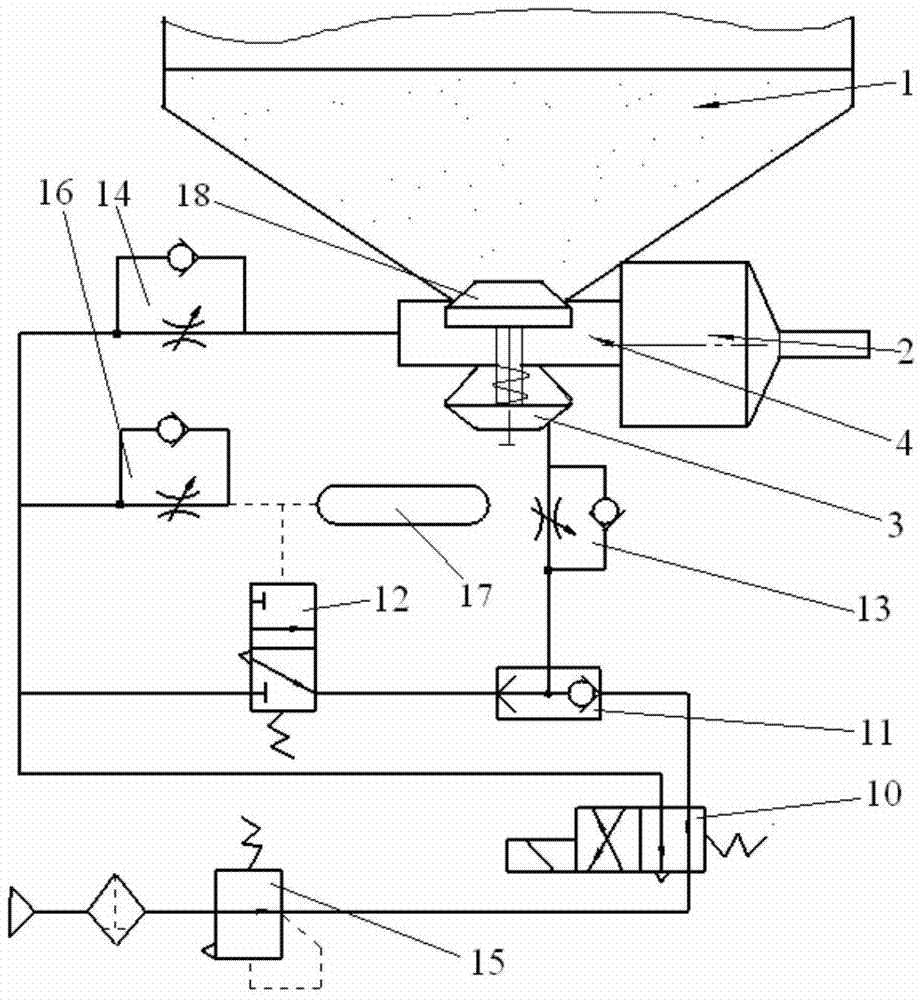
[0034] Such as figure 1 , figure 2 The structure of the present invention expressed is a pipe mold powder spraying machine, including a large hopper 1 and an air pressure system. The technical key points of the present invention are mechanical structure and control method.

[0035] In order to solve the problems existing in the prior art and overcome its defects, and realize the invention purpose of reducing faults and improving production efficiency, the technical scheme adopted by the present invention is:

[0036] Such as figure 1 , figure 2 As shown, in the pipe mold powder spraying machine of the present invention, an in...


PUM


Abstract

The invention discloses a working method of a pipe powder spraying machine. The pipe powder spraying machine comprises a large hopper (1) and a pneumatic system. A spraying pipe (4) is arranged under the large hopper (1). The spraying pipe (4) is connected with a pipe powder spraying air channel of the pneumatic system. By the adoption of the technical scheme, a pneumatic control transmission technique is adopted, complex mechanical transmission is omitted, the cost for replacing abraded pieces is reduced, and the production efficiency is improved.

Description

technical field [0001] The invention belongs to the technical field of cast pipe production equipment. More specifically, the present invention relates to a working method of a tube mold powder spraying machine. Background technique [0002] In water-cooled metal mold casting, it is often necessary to add silicon barium powder, also known as tube mold powder, to the metal mold, and its particle size is 0-0.3mm. The amount added is generally determined according to the surface area of ​​the pipe mold. Powder delivery is generally achieved using a mechanical device screw or a combination of screw pressurized air. In the prior art, there are two ways of conveying the pipe mold powder: [0003] One method is: the hopper is under the iron drop chute of the taphole, and the hydraulic motor drives the screw rod more than 6m long below the launder to send the pipe mold powder into the pipe mold. Due to the small feeding port of this device, it is inconvenient to feed materials, ...

Claims


Application Information

Patent Timeline
Patent Type & Authority Patents(China)
IPC IPC(8): B22C23/02
CPCB22C23/02
Inventor 李红军吕少峰张永明岳江峰金时兴
Owner WUHU XINXING DUCTILE IRON PIPES
Why Eureka
Try Eureka