Chamfering device for valve body

A technology of chamfering device and valve body, applied in positioning device, clamping, supporting and other directions, can solve the problems of cumbersome tool stroke and increase production cost, and achieve the effect of saving manpower and material resources, saving production cost and reducing production time.

Inactive Publication Date: 2016-02-10
WUHU HENGHAO MACHINERY MFG
View PDF6 Cites 2 Cited by
  • Summary
  • Abstract
  • Description
  • Claims
  • Application Information

AI Technical Summary

Problems solved by technology

Although this method is convenient to use, two tools need to be replaced during the chamfering process of the valve body, and the tool stroke is more cumbersome, which greatly increases the production cost

Method used


Image

  • Chamfering device for valve body
  • Chamfering device for valve body

Examples


Embodiment Construction

[0016] In order to make the purpose, technical solutions and beneficial effects of the present invention more clear, the preferred embodiments of the present invention will be described in detail below in conjunction with the accompanying drawings, and the present invention will be further described to facilitate the understanding of technical personnel.

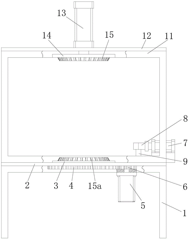
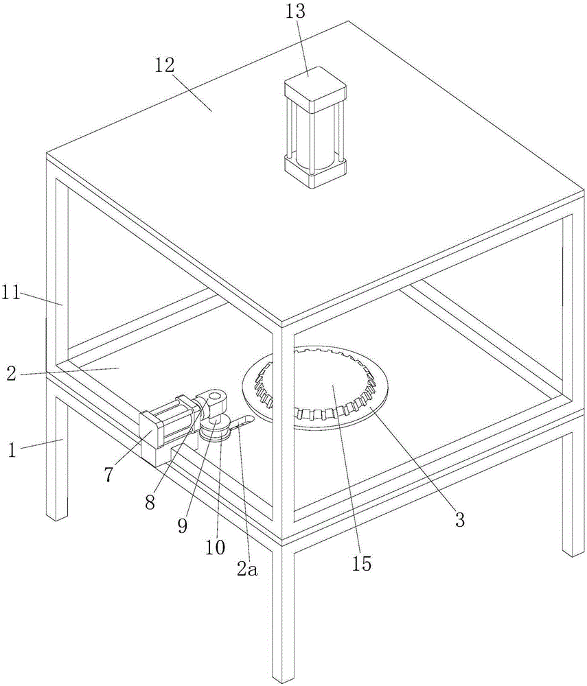
[0017] Such as Figure 1 to Figure 2 As shown, a chamfering device for a valve body includes a support frame 1, the upper end of the support frame 1 is fixed with a lower end plate 2, the middle part of the lower end plate 2 is provided with a lower positioning seat 3, and the lower positioning seat 3 A ring gear 4 is fixed on the outer wall of the lower end plate 2, a motor 5 is installed on the lower end of the lower end plate 2, and a gear 6 is fixed on the shaft of the motor 5, and the gear 6 is meshed with the ring gear 4. When in use, the motor 5 works to drive the gear 6 to rotate, the gear 6 drives the ring gear 4 to...


PUM


Abstract

The invention discloses a chamfering device for a valve body. The chamfering device for the valve body comprises a supporting frame. A lower end plate is fixed to the upper end of the supporting frame. A lower positioning seat is arranged in the middle of the lower end plate. A gear ring is fixed to the outer wall of the lower positioning seat. A first air cylinder is installed on the right of the lower end plate, a connecting block is fixed to the left end of the first air cylinder, a connecting rod is fixed to the connecting block, and a chamfering wheel is fixed to the outer wall of the connecting rod. A supporting framework is fixed to the upper end of the lower end plate, an upper end plate is fixed to the upper end of the supporting framework, a second air cylinder is installed on the upper end plate, and an upper positioning seat is fixed to the lower end of the second air cylinder. Circular truncated cone shaped positioning blocks are fixed to the upper positioning seat and the lower positioning seat. The chamfering device for the valve body has the advantages of being simple in structural design, convenient to use and the like. A flange of the valve body is chamfered through the chamfering wheel, the chamfering efficiency of the valve body is improved, the production time is shortened, and the production cost is reduced. The circular truncated cone shaped positioning blocks are used for positioning the valve body, the positioning efficiency is improved, and manpower and material resources are saved.

Description

technical field [0001] The invention relates to the technical field of valve body chamfering equipment, in particular to a valve body chamfering device. Background technique [0002] With the improvement of our country's consumption level, our country's auto industry has made great progress. During the operation of the car, the car hydraulic valve is an important part of the car brake system. As of 2013, there are more than 200,000 auto parts manufacturing enterprises in my country, and as many as 16,000 major auto parts manufacturing enterprises, including more than 10,000 enterprises above designated size, and more than 1,200 foreign-funded enterprises. Therefore, every enterprise must improve its own production technology in order to be competitive in the market. [0003] The valve is an important control component in the fluid transportation system, which has the functions of cut-off, diversion, adjustment, pressure stabilization, and flow diversion. During the produc...

Claims


Application Information

Patent Timeline
Patent Type & Authority Applications(China)
IPC IPC(8): B23D79/02B23Q3/08B23Q7/02
Inventor 袁道华
Owner WUHU HENGHAO MACHINERY MFG
Why Eureka
Try Eureka