Double-end chamfering machine

A double-head chamfering machine and frame technology, which is applied to metal processing machinery parts, clamping, supporting and other directions, can solve the problems of reducing the processing efficiency of pipe chamfering, and it is difficult to ensure the consistency of chamfering accuracy at both ends of the round pipe. Achieve the effect of improving the efficiency of chamfering, improving convenience, and improving the accuracy of chamfering

Pending Publication Date: 2018-03-06
汉升机械(江苏)有限公司
View PDF10 Cites 2 Cited by
  • Summary
  • Abstract
  • Description
  • Claims
  • Application Information

AI Technical Summary

Problems solved by technology

[0002] Pipes are widely used in the processing and manufacturing industry. After the pipes are cut, there will be burrs on the cut end. Therefore, in order to remove the burrs on the pipes or to facilitate the welding of the pipes, it is necessary to use a chamfering machine for the pipes. The end of the pipe is chamfered, but the existing chamfering machine can only chamfer one end of the pipe first, and then chamfer the other end of the pipe. The feed rate of the tool at the corner is controlled by the operator, it is difficult to ensure the consistency of the chamfering accuracy at both ends of the round pipe, and it also reduces the processing efficiency of the pipe chamfering

Method used

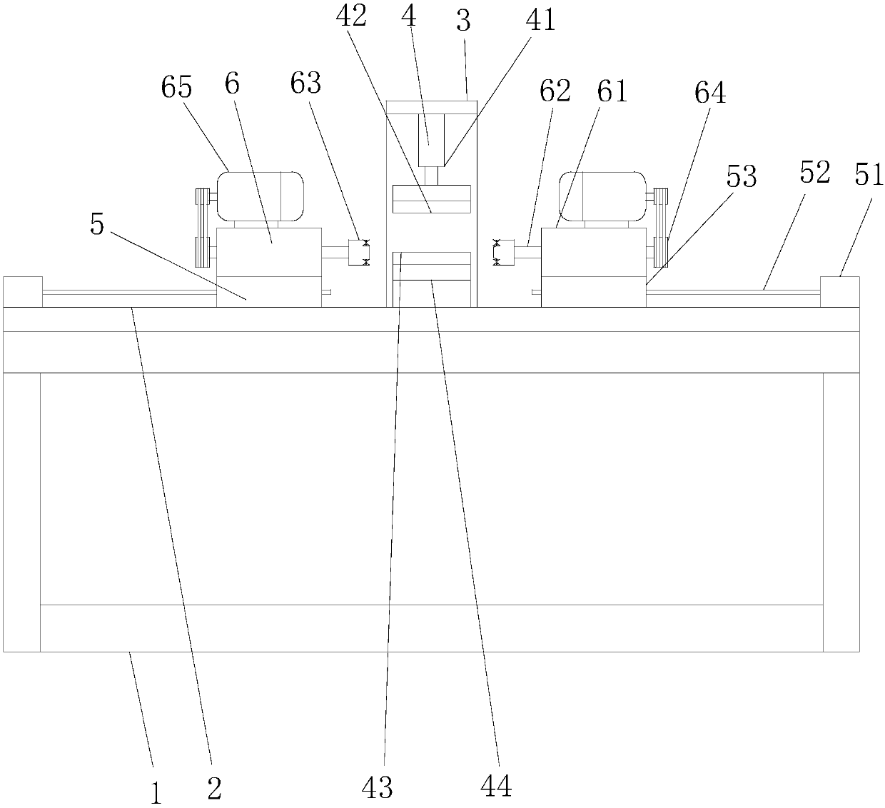
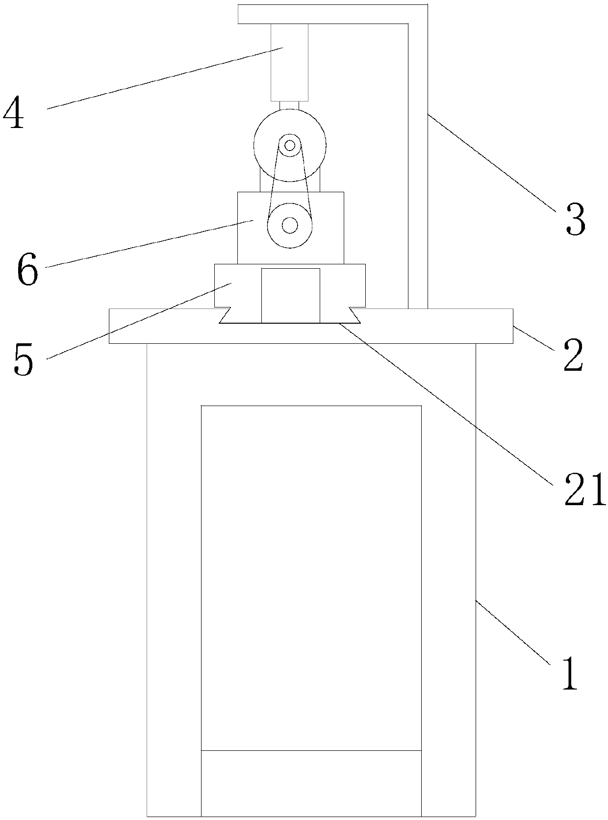
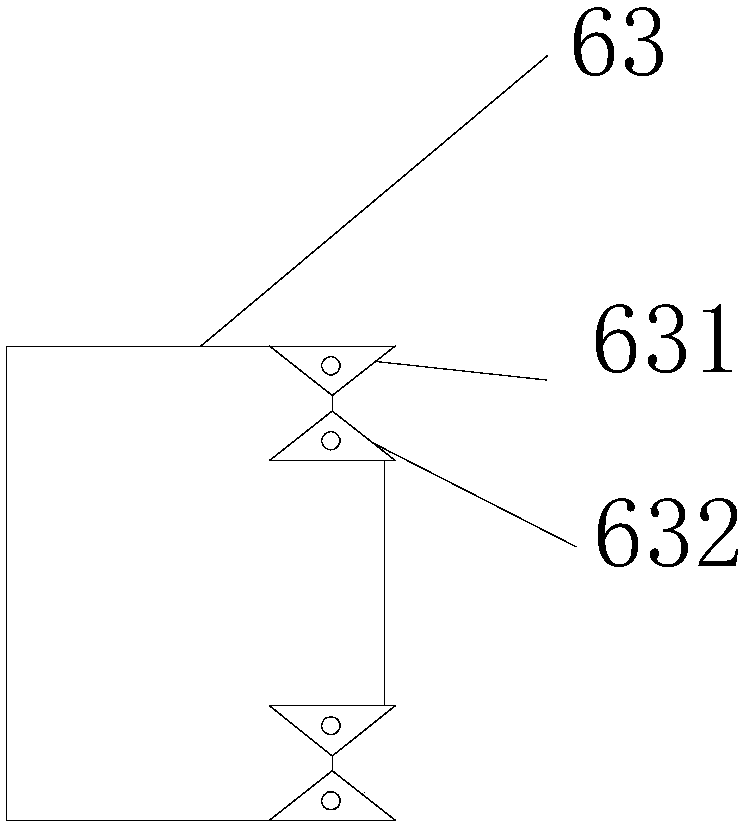

Image

  • Double-end chamfering machine
  • Double-end chamfering machine
  • Double-end chamfering machine

Examples


Embodiment Construction

[0014] The specific implementation manners of the present invention will be further described below in conjunction with the accompanying drawings, so as to make the technical solution of the present invention easier to understand and grasp.

[0015] In this embodiment, it should be understood that the terms "middle", "upper", "lower", "top", "right side", "left end", "above", "back", "middle", etc. The indicated orientation or positional relationship is based on the orientation or positional relationship shown in the drawings, and is only for the convenience of describing the present invention, rather than indicating or implying that the referred device or element must have a specific orientation, be constructed and operated in a specific orientation , and therefore cannot be construed as a limitation of the present invention.

[0016] In addition, in this specific embodiment, if the connection or fixing method between the components is not specified in particular, the connect...


PUM


Abstract

The invention discloses a double-end chamfering machine. The double-end chamfering machine comprises a rack, a base arranged above the rack and sliding grooves formed in the base. An inverted-L-shapedlongitudinal beam is arranged in the middle of the base. A clamping device for fixing a pipe to be chamfered is arranged below the top of the longitudinal beam. Sliding devices are correspondingly arranged at the two ends of the base. A cutting device is arranged on each sliding device. Each sliding device comprises a stepping motor, a lead screw and a sliding block. The stepping motors are fixedly connected with the base. The sliding blocks are located in the sliding grooves of the base. One end of each lead screw is connected with the corresponding stepping motor, and the other end of eachlead screw is connected with the corresponding sliding block. The double-end chamfering machine has the beneficial effects that the two ends can be chamfered at the same time, the chamfering accuracyis high, and the chamfering machining efficiency of the pipe is improved.

Description

technical field [0001] The invention relates to the technical field of pipe processing equipment, in particular to a double-head chamfering machine. Background technique [0002] Pipes are widely used in the processing and manufacturing industry. After the pipes are cut, there will be burrs on the cut end. Therefore, in order to remove the burrs on the pipes or to facilitate the welding of the pipes, it is necessary to use a chamfering machine for the pipes. The end of the pipe is chamfered, but the existing chamfering machine can only chamfer one end of the pipe first, and then chamfer the other end of the pipe. The feed rate of the tool at the corner is controlled by the operator, it is difficult to ensure the consistency of the chamfering accuracy at both ends of the round pipe, and it also reduces the processing efficiency of the pipe chamfering. Contents of the invention [0003] In view of this, the object of the present invention is to provide a double-head chamfer...

Claims


Application Information

Patent Timeline
IPC IPC(8): B23D79/00B23Q3/08B23Q5/28B23Q5/40
CPCB23D79/00B23Q3/082B23Q5/28B23Q5/40
Inventor 陶峰
Owner 汉升机械(江苏)有限公司
Why Eureka
Try Eureka