Novel exhaust valve

An exhaust valve, a new type of technology, applied in the direction of valve device, function valve type, valve for ventilation, etc., can solve the problems of low safety and stability, chemical corrosion, staff injury, etc., and achieve high safety and stability, extended The service life and the effect of avoiding chemical corrosion

Inactive Publication Date: 2016-02-10
天津市精沃阀门科技有限公司
View PDF0 Cites 3 Cited by
  • Summary
  • Abstract
  • Description
  • Claims
  • Application Information

AI Technical Summary

Problems solved by technology

The exhaust port of the existing exhaust valve is directly in contact with the external environment. During use, if the gas pressure in the exhaust pipe is too high, the gas will become a high-speed airflow and be ejected from the exhaust port. When it comes out, there is also a small amount of liquid impurities and solid impurities, which will cause certain high-temperature corrosion and chemical corrosion to the equipment near the exhaust valve, thereby affecting the service life of the entire pipeline system, and may also cause certain harm to the nearby staff. injury, its safety and stability are low

Method used


Image

  • Novel exhaust valve

Examples


Embodiment 1

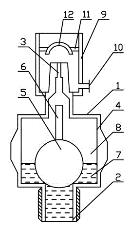
[0011] The present invention includes a valve body 1, an installation port 2, an exhaust port 3, a floating cavity 4, a floating ball 5, a connecting rod 6, a liquid 7, a gas 8, a liquid storage tank 9, a liquid discharge port 10, a mounting frame 11, a hemispherical stop Plate 12, the lower end of the valve body 1 is the installation port 2, the upper end is the exhaust port 3, the inner cavity of the valve body 1 is the floating cavity 4, the connecting rod 6 is installed on the upper end of the floating ball 5, and then the floating ball 5 is installed Inside the floating chamber 4, the connecting rod 6 is connected to the lower end of the exhaust port 3, and then a liquid discharge port 10 is opened on the liquid storage tank 9, and the hemispherical baffle 12 is installed on the liquid storage tank 9 through the mounting bracket 11. Then install the liquid storage tank 9 on the upper end of the exhaust port 3, so that the hemispherical baffle 12 is at the normal end of the...

Embodiment 2

[0013] When in use, the exhaust valve is installed on the upper end of the fluid pipeline through the installation port 2, the fluid in the pipeline enters the floating chamber 4 from the installation port 2, and the floating ball 5 moves up and down with the liquid level in the floating chamber 4, so that the connecting rod 6 Move up and down in the exhaust port 3, close or open the exhaust port 3 to exhaust, the airflow from the exhaust port 3 impacts the hemispherical baffle 12 to disperse, and overflows from the upper opening of the liquid storage tank 9 , the liquid 7 and impurities flowing into the liquid storage tank 9 are discharged through the liquid discharge port 10 .


PUM


Abstract

The invention provides a novel exhaust valve capable of preventing splashing. The novel exhaust valve comprises a valve body, a mounting port, an exhaust port, a floating cavity, a floating ball, a connection rod, a liquid, gas, a liquid storage box, a liquid discharge port, a mounting rack and a hemispherical baffle, wherein the mounting port is formed in the lower end of the valve body; the upper end of the valve body is the exhaust port; the inner cavity of the valve body is the floating cavity; the floating ball is arranged in the floating cavity; the connection rod is arranged at the upper end of the floating ball and connected with the lower end of the exhaust port where the connection rod is inserted; a liquid and gas are accommodated in the floating cavity; the gas is located above the liquid; the liquid storage box is arranged at the upper end of the exhaust port. The liquid storage box is additionally arranged at the upper end of the exhaust port, the spherical baffle is mounted in the liquid storage box and can disperse exhaust gas flow, the situation that workers are harmed by high-temperature gas flow sprayed out at a high speed is avoided, and the safety and the stability are high.

Description

technical field [0001] The invention relates to the field of valves, in particular to a novel exhaust valve. Background technique [0002] The exhaust valve is an indispensable auxiliary component in the pipeline system. It is widely used in pipeline exhaust fields such as independent heating systems, central heating systems, and heating boilers. It is often installed at commanding heights or elbows to remove excess gas in the pipeline and improve Pipeline efficiency and reduce energy consumption. The exhaust port of the existing exhaust valve is directly in contact with the external environment. During use, if the gas pressure in the exhaust pipe is too high, the gas will become a high-speed airflow and be ejected from the exhaust port. When it comes out, there is also a small amount of liquid impurities and solid impurities, which will cause certain high-temperature corrosion and chemical corrosion to the equipment near the exhaust valve, thereby affecting the service lif...

Claims


Application Information

Patent Timeline
Patent Type & Authority Applications(China)
IPC IPC(8): F16K24/04
Inventor 李继元
Owner 天津市精沃阀门科技有限公司
Why Eureka
Try Eureka