Electrical connector for circuit boards

A technology of electrical connectors and circuit boards, applied in the direction of circuits, connections, parts of connection devices, etc., can solve problems such as damage, plug connector drop-off, deformation, etc., to prevent accidental drop-off, deformation and damage, and reliable maintenance The effect of the lock function

Active Publication Date: 2016-02-10
HIROSE ELECTRIC GROUP
View PDF4 Cites 8 Cited by
  • Summary
  • Abstract
  • Description
  • Claims
  • Application Information

AI Technical Summary

Problems solved by technology

Therefore, when an excessive pull-out force is inadvertently applied to the plug connector in the connector-fitting state, there is a possibility that the end wall side lock arm portion and the side wall side lock arm portion hold the locked target connector by the lock portion. There is a possibility that the locked state of the corresponding lock part will be forcibly lifted in the direction of connector extraction, causing deformation and damage, and there is also a possibility that the plug connector may fall off

Method used


Image

  • Electrical connector for circuit boards
  • Electrical connector for circuit boards
  • Electrical connector for circuit boards

Examples


no. 1 approach

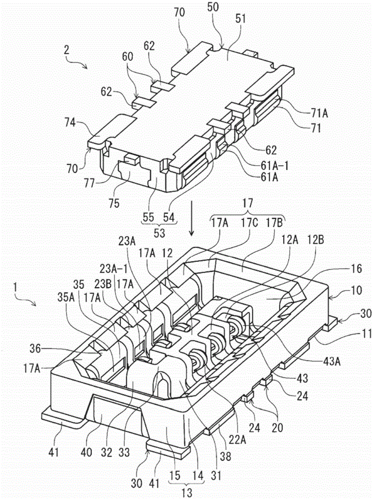
[0033] figure 1 It is a perspective view of the receptacle connector 1 according to the first embodiment of the present invention and the plug connector 2 fitted to the receptacle connector from above, and shows a state before the connectors are fitted. The receptacle connector 1 and the plug connector 2 of the present embodiment are electrical connectors for circuit boards respectively arranged on the mounting surfaces of different circuit boards (not shown), and are configured so as to be opposite to the mounting surfaces of the circuit boards. Direction at right angles ( figure 1 The up and down direction in the figure) is the connector assembly in the plugging and unplugging direction. In this embodiment, the fitting direction of the plug connector 2 with respect to the receptacle connector 1, that is, the figure 1 The direction in which the plug connector 2 moves downward is defined as the "connector fitting direction", and the opposite direction, that is, figure 1 The...

no. 2 approach

[0084] In the first embodiment, for the socket lock 30, the locking plate portion 35 and the side rising surface reinforcing plate portion 31 are connected via the connecting bottom portion 34, but in the second embodiment, the locking plate portion and the end rising It is different from 1st Embodiment in that a surface reinforcement board part is connected via the connection bottom part.

[0085] Figure 6A It is a perspective view which shows the receptacle lock 130 which concerns on 2nd Embodiment. Below, based on Figure 6A A second embodiment will be described. In this embodiment, the description will focus on the parts different from the first embodiment, and for the same parts as the first embodiment, the figures in which "100" is added to the reference numerals in the first embodiment are attached. Mark and omit its description.

[0086] Such as Figure 6A As shown, in addition to the locking plate portion 135 (hereinafter referred to as “side locking plate porti...

no. 3 approach

[0092] In the first embodiment, the side rising surface reinforcing plate portion 31 of the socket lock 30 is provided only on one side of the protruding wall 12, and on the other side (the side where the power contact arm portion 43 is provided) Since the side rising surface reinforcing plate portion is not provided, the lock plate portion facing the other side surface is not connected to the lock piece portion held by the protruding wall 12 . On the other hand, in the third embodiment, a side rising surface reinforcing plate portion is also provided on the other side surface side of the protruding wall 12 so that the locking plate portion facing the other side surface stands up from the side surface. It differs from the first embodiment in that the surface reinforcing plate portions are connected.

[0093] Figure 6B It is a perspective view which shows the receptacle lock 230 which concerns on 3rd Embodiment. Below, based on Figure 6B A third embodiment will be describe...


PUM


Abstract

To provide an electrical connector for circuit boards having lock fittings designed to reliably prevent damage to lock portions and inadvertent removal of mating connectors. The lock fittings (30) have lock plate portions (35) that extend along the inner surface of the lateral walls of the housing and are retained in place on said lateral walls, or which extend along the inner surface of the end walls and are retained in place on said end walls; upright face-reinforcing plate portions (31) that extend along the upright faces of the protruding wall of the housing facing said lock plate portions (35) and are retained in place on said protruding wall; and connecting bottom portions (34) that extend along the bottom wall and connect the bottom wall-adjacent end portions of the lock plate portions (35) and the upright face-reinforcing plate portions (31).

Description

technical field [0001] The invention relates to an electrical connector for a circuit board, which is arranged on a mounting surface of a circuit board and uses a direction at right angles to the mounting surface as the connector insertion and extraction direction for plugging and unplugging of a target connector. An electrical connector for circuit boards with a locking member capable of locking a mating connector in the direction in which the connector is pulled out. Background technique [0002] As such an electrical connector for a circuit board, for example, a receptacle connector described in Patent Document 1 is known. In Patent Document 1, the receptacle connector has a housing arranged on the mounting surface of the circuit board and extending in a direction parallel to the mounting surface as a longitudinal direction, and the housing is aligned and held in the housing with the longitudinal direction as the terminal arrangement direction. A plurality of terminals a...

Claims


Application Information

Patent Timeline
Patent Type & Authority Applications(China)
IPC IPC(8): H01R13/629H01R13/639H01R13/502
CPCH01R12/716H01R13/20H01R13/6271H01R12/7076
Inventor 长谷川洋平
Owner HIROSE ELECTRIC GROUP
Why Eureka
Try Eureka