Impact type diaphragm micro jet dispensing device

A dispensing device and impact-type technology, which is applied in the field of impact-type diaphragm micro-spray dispensing devices, can solve problems such as nozzle wear, increased maintenance costs of jet dispensing devices, and liquid material changes, so as to avoid severe wear and direct Contact, the effect of reducing the cost of use

Inactive Publication Date: 2016-02-17
CHANGZHOU GAO KAI PRECISION MACHINERY CO LTD
View PDF6 Cites 7 Cited by
  • Summary
  • Abstract
  • Description
  • Claims
  • Application Information

AI Technical Summary

Problems solved by technology

The direct collision between the firing pin and the nozzle will cause severe wear of the nozzle, which greatly increases the maintenance cost of the jet dispensing device. At the same time, the firing pin type jet dispensing device will destroy the glue when spraying glue with solid particles (such as conductive silver paste). Solid particles in the liquid, resulting in changes in the liquid material
So far, there is no device that can reduce the cost of spraying equipment and achieve precise spraying of liquids with particles

Method used


Image

  • Impact type diaphragm micro jet dispensing device
  • Impact type diaphragm micro jet dispensing device
  • Impact type diaphragm micro jet dispensing device

Examples


Embodiment Construction

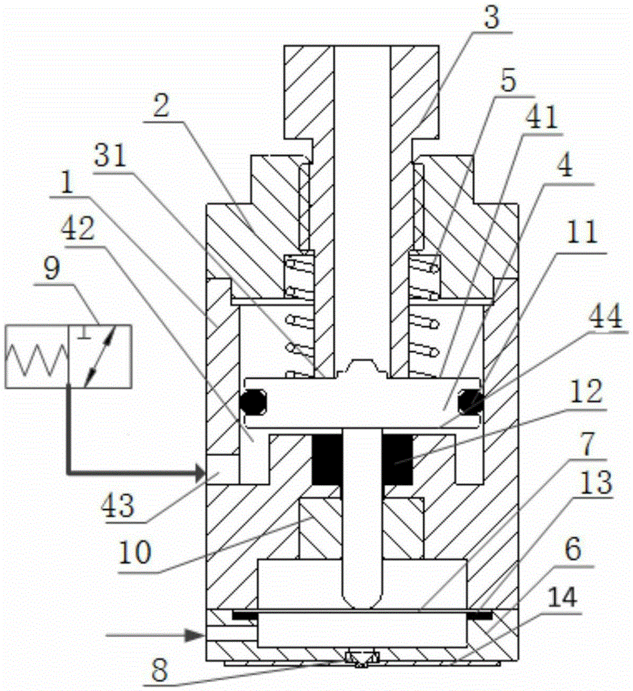
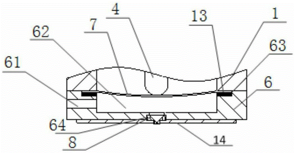
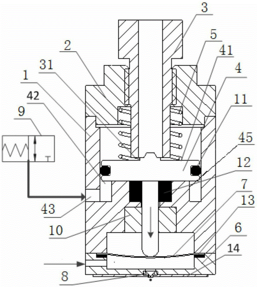
[0018] Such as figure 1 As shown, the present invention discloses an impact-type diaphragm micro-spray dispensing device, including a cylinder 1, a gland 2, a stroke adjustment rod 3, a piston rod 4, a spring 5, an injection chamber 6, a diaphragm 7, a nozzle 8 and High-frequency solenoid valve 9, gland 2 is installed above the cylinder 1, the stroke adjustment rod 3 is installed in the gland 2 through threads, the piston rod 5 is installed in the cylinder 1, and the spring 5 is installed between the gland 2 and the piston rod 4 Between, the spring 5 is pressed on the upper end surface 41 of the piston rod, the piston rod 4 is located under the stroke adjustment rod 3, the injection chamber 6 is installed under the cylinder 1, and the diaphragm 7 is sandwiched between the injection chamber 6 and the cylinder 1, The diaphragm 7 is located below the piston rod 4 , the nozzle 8 is installed on the lower end surface of the injection chamber 6 , and the high-frequency solenoid valv...


PUM


Abstract

The invention relates to dispensing devices, particularly to an impact type diaphragm micro jet dispensing device which comprises an air cylinder, a gland, a stroke adjustment lever, a piston rod, springs, a jet chamber, a diaphragm, a nozzle and a high-frequency electromagnetic valve, wherein the gland is mounted above the air cylinder; the stroke adjustment lever is mounted in the gland through screw threads; the piston rod is arranged in the air cylinder; the springs are arranged between the gland and the piston rod, and are pressed on the upper end surface of the piston rod; the piston rod is positioned below the stroke adjustment lever; the jet chamber is mounted below the air cylinder; the diaphragm is mounted between the jet chamber and the air cylinder in a clamping manner, and is positioned below the piston rod; the nozzle is mounted on the lower end surface of the jet chamber; and the high-frequency electromagnetic valve is communicated with the air cylinder. According to the impact type diaphragm micro jet dispensing device, the impact force of the piston rod is transferred to the liquid in the jet chamber through the diaphragm, and the direct contact of the piston rod and the nozzle and the glue liquor is avoided, so that the particles in the glue liquor are not damaged during the jet of the glue liquor containing particles, the severe abrasion of the nozzle is avoided, and the use cost is reduced.

Description

technical field [0001] The invention relates to a dispensing device, in particular to an impact type diaphragm micro spray dispensing device. Background technique [0002] Fluid dispensing, the process of precisely dispensing fluids in a controlled manner, is a key technology in the electronics packaging industry. Traditional contact dispensing technology relies on dispensing needles to adhere the glue to the substrate. Compared with the contact dispensing method, the non-contact jet dispensing technology has the advantages of fast dispensing speed, small size of glue dots, high consistency of glue dots, strong operation flexibility, and no need for Z-axis movement. [0003] However, most of the micro-spray dispensing devices currently on the market or currently being researched by scholars use a striker nozzle structure. The striker moves at a high speed and hits the nozzle, so that the liquid at the nozzle forms a local high pressure and then sprays out through the nozzle...

Claims


Application Information

Patent Timeline
Patent Type & Authority Applications(China)
IPC IPC(8): B05C5/00B05C11/10
Inventor 顾守东刘建芳王吉举王全伟孙立权吴亚东王迪江海焦晓阳路崧
Owner CHANGZHOU GAO KAI PRECISION MACHINERY CO LTD
Why Eureka
Try Eureka