Fire extinguisher valve structure

A technology for fire extinguishers and valves, applied in valve details, valve devices, fire rescue, etc., can solve the problems of users' physical fatigue and achieve the effect of saving energy

Active Publication Date: 2021-10-08
绍兴嘉元消防设备有限公司
View PDF6 Cites 0 Cited by
  • Summary
  • Abstract
  • Description
  • Claims
  • Application Information

AI Technical Summary

Problems solved by technology

[0003] Existing fire extinguisher valves require greater grip strength, which hinders the elderly and children when using the fire extinguisher. In addition, even if it can be used normally, pressing it for a long time will cause the user to be physically tired

Method used


Image

  • Fire extinguisher valve structure
  • Fire extinguisher valve structure
  • Fire extinguisher valve structure

Examples


Embodiment Construction

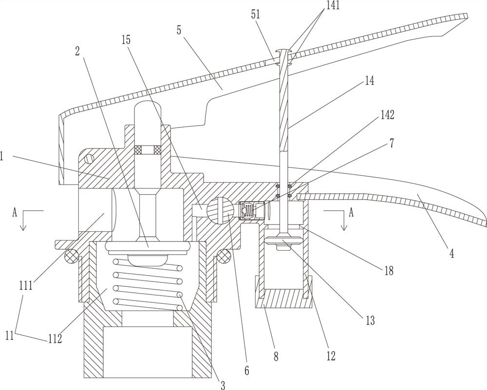
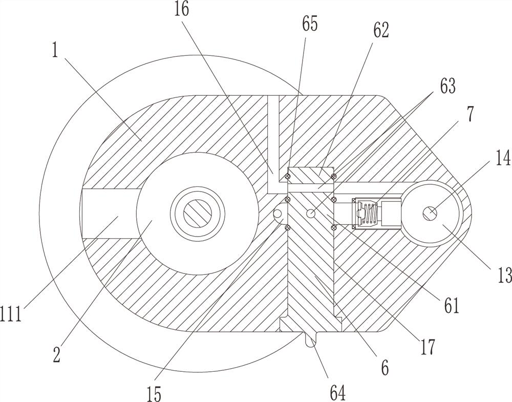
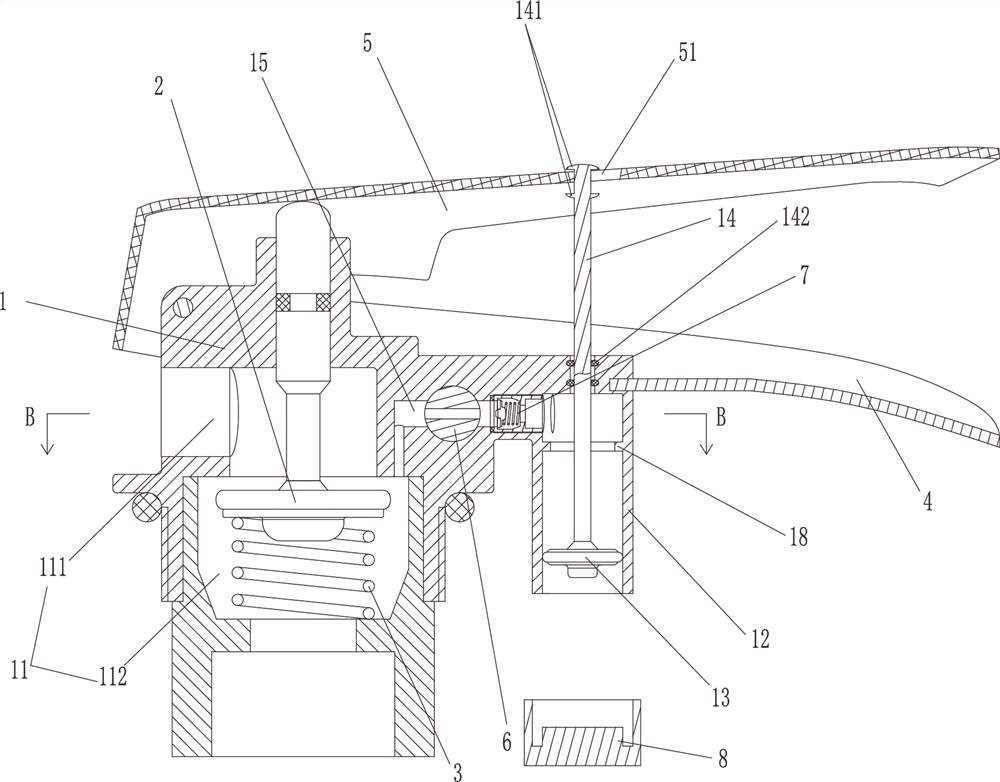
[0020] The present invention will be further described in connection with the accompanying drawings and specific embodiments: see Figure 1 to 4 A fire extinguisher valve structure includes a valve seat 1, a spool 2, a spring 3, a fixing arm 4, and a rotating arm 5, and a spray passage 11 is provided on the valve seat 1, and the actuator is disposed on the valve seat 1. The spool 2, the spring 3 pushes the spray passage 11 to block the jet passage 11 and the injection passage 11 is separated into a low pressure passage 111 communicating with the injection port, and the high pressure passage 112 communicating with the cylinder, the top of the spool 2 is located below the rotating arm 5, rotate The arm 5 is rotated on the valve seat 1, and the fixing arm 4 is fixed to the valve seat 1, and the piston jacket 12 having a bottom opening is provided on the valve seat 1, and the piston sleeve 12 is provided with a piston 13, and the piston 13 is connected to the link 14. The connecting ro...


PUM


Abstract

The invention discloses a fire extinguisher valve structure. The fire extinguisher valve structure comprises a valve seat, a valve element, a spring, a fixed arm and a rotating arm, wherein a spraying channel is formed in the valve seat; the spring pushes the valve element to block the spraying channel and divides the spraying channel into a low-pressure channel communicating with a spraying opening and a high-pressure channel communicating with a steel cylinder; a piston sleeve with an opening in the bottom is arranged on the valve seat; a piston is movably arranged in the piston sleeve and connected with a connecting rod; the connecting rod penetrates out of the top of the piston sleeve and penetrates through a kidney-shaped hole in the rotating arm; limiting blocks are arranged on positions, located on the two sides of the rotating arm, the connecting rod; a cavity defined by the piston and the top of the piston sleeve is connected with a first channel communicated with the high-pressure channel and a second channel communicated with the external atmosphere; and the first channel and the second channel are provided with a first valve element part and a second valve element part respectively. The valve structure of the fire extinguisher can be held for spraying by hands and can also perform automatic spraying, large grip strength is not needed during automatic spraying, physical strength can be saved, and old people and children with small grip strength can also easily carry out spraying.

Description

Technical field [0001] The invention belongs to the technical field of fire extinguisher valve, in particular, a fire extinguisher valve structure, in particular a powerful fire extinguisher valve structure. Background technique [0002] The fire extinguisher is a portable fire extinguishing tool. The fire extinguisher is placed in a fire extinguisher. It is used to save the fire. The fire extinguisher is one of the common fire protection facilities. The components stored in the public place or possible fires, different types of fire extinguishers Different, it is designed for different fires and must pay attention to avoiding anti-effect and danger. [0003] Existing fire extinguisher valves require a large grip, which makes the elderly and children have a certain obstacle when using fire extinguishers, and even if it can be used normally, the use of long-term pressing can cause the user to be exhausted. Inventive content [0004] The present invention provides a fire extinguis...

Claims


Application Information

Patent Timeline
Patent Type & Authority Applications(China)
IPC IPC(8): F16K5/04F16K5/08F16K21/16F16K35/06A62C13/64
CPCF16K35/06F16K5/0442F16K5/08F16K21/16A62C13/64
Inventor 田超
Owner 绍兴嘉元消防设备有限公司
Why Eureka
Try Eureka