
Workpiece conveying device and machine tool

A technology of conveying device and workpiece, applied in metal processing machinery parts, manipulators, metal processing and other directions, can solve the problems of shortening the time required for workpiece conveying, shortening the moving time of the sliding body, hindering the acceleration and deceleration of the sliding body, etc.

Inactive Publication Date: 2016-02-17
MURATA MASCH LTD
View PDF1 Cites 1 Cited by
  • Summary
  • Abstract
  • Description
  • Claims
  • Application Information

AI Technical Summary

Problems solved by technology

[0004] However, in the structure in which the drive source is provided on the slider as described above, the mass of the drive source is added in addition to the mass of the slider, and therefore, rapid acceleration and deceleration of the slider are hindered.
This situation is an obstacle to shortening the moving time of the slider, and further shortening the time required for conveying the workpiece.

Method used


Image

  • Workpiece conveying device and machine tool
  • Workpiece conveying device and machine tool
  • Workpiece conveying device and machine tool

Examples


no. 1 Embodiment approach >

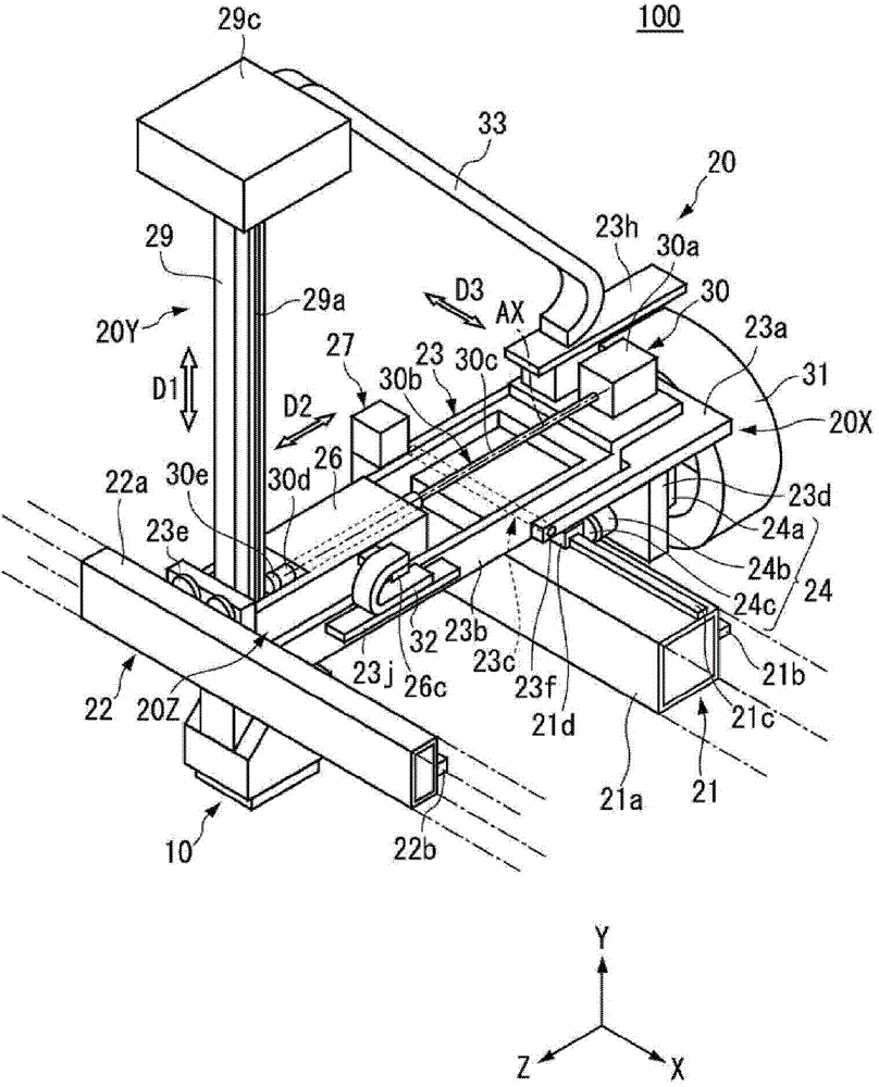
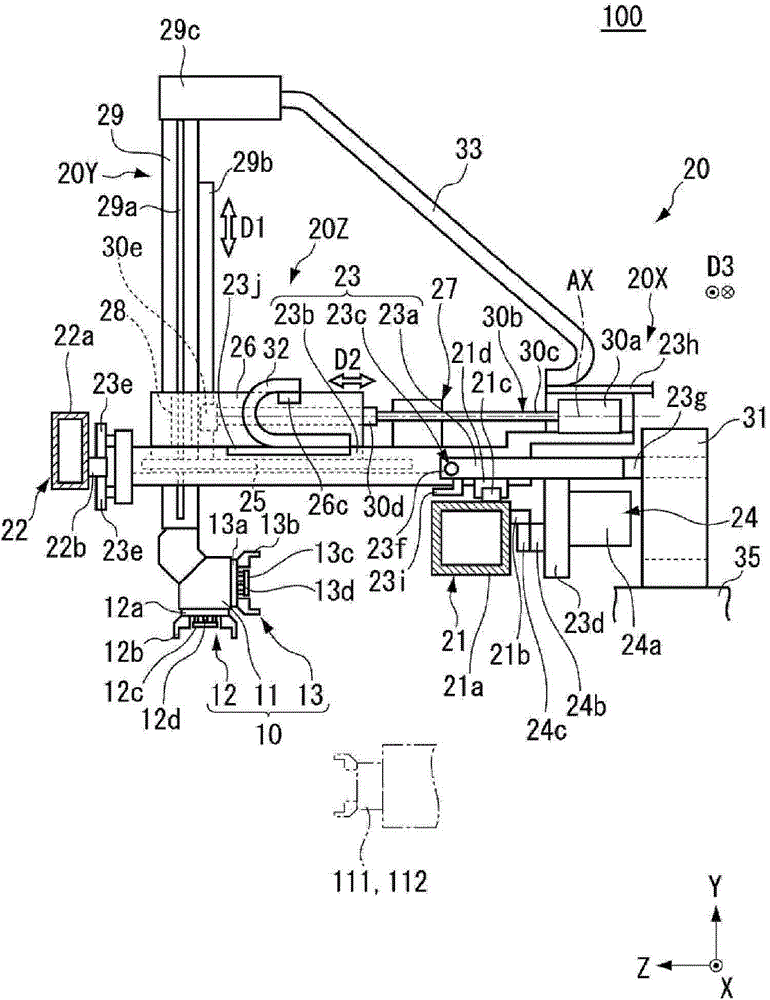
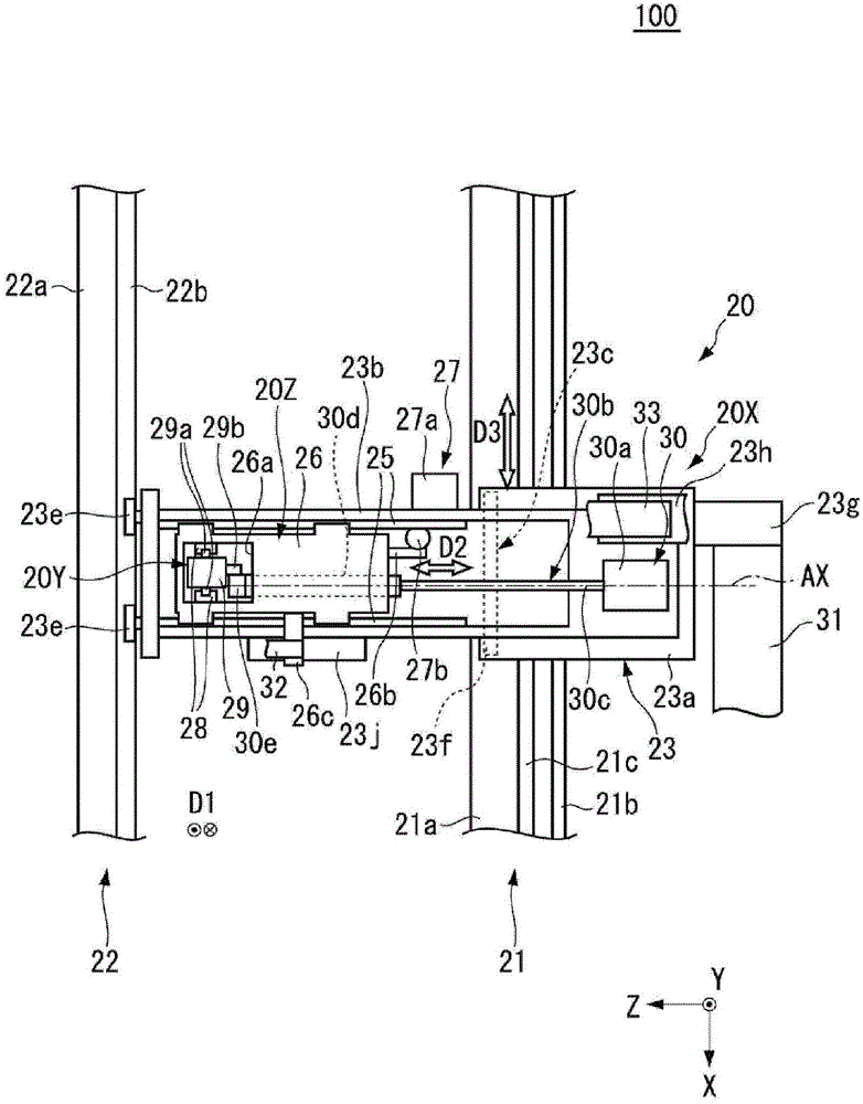
[0025] figure 1 It is a perspective view which shows an example of the workpiece conveyance apparatus 100 which concerns on 1st Embodiment. figure 2 It is a side view showing an example of the workpiece transfer device 100 . image 3 It is a plan view showing an example of the workpiece transfer device 100 . However, in order to easily identify the structure of the workpiece transfer device 100, for example, in Figure 1 ~ Figure 3 In , a part of the workpiece transfer device 100 is shown in cross section, or partially omitted from the illustration.

[0026] Such as Figure 1 ~ Figure 3 As shown, the workpiece transfer device 100 includes a workpiece holding unit 10 and a moving mechanism 20 . The workpiece transfer device 100 is used mounted on, for example, a machine tool described later, and the spindles 111, 112 ( figure 2 The workpiece W is conveyed between the dotted line in ) and the workpiece loading and unloading part (not shown).

[0027] Such as figure 2 A...

no. 2 Embodiment approach >

[0069] Next, a second embodiment will be described. In the second embodiment, a machine tool including the workpiece transfer device 100 described in the first embodiment will be described as an example. In the second embodiment, description will be made using the XYZ rectangular coordinate system common to the first embodiment. However, in the second embodiment, the direction of the rotation shafts of the main shafts 111 and 112 is referred to as the Z direction, and the direction for defining the cutting amount with respect to the workpiece W is referred to as the X direction.

[0070] Figure 8 It is a figure which shows an example of the machine tool 200 which concerns on 2nd Embodiment. Figure 8 The machine tool 200 shown is, for example, a parallel 2-axis lathe. exist Figure 8 In the figure, the +Z side of the machine tool 200 is the front side, and the −Z side is the back side. Also, the ±X sides of the machine tool 200 are side surfaces, and the X direction is t...


PUM


Abstract

Provided are a workpiece conveying device (100) and a machine tool that can reduce time required to convey a workpiece. The workpiece conveying device (100) includes an elevating section (29) that includes a chuck (12, 13) for holding the workpiece, a slider (26) that supports the elevating section (29) such that the elevating section (29) is movable in a first direction (D1), the slider (26) being movable in a second direction (D2) different from the first direction (D1), and a driving section (30) that drives the elevating section (29), wherein the driving section (30) includes a driving source (30a) disposed away from the elevating section (29) and the slider (26), and a transmitting section (30b) that transmits a driving force of the driving source (30a) to the elevating section (29).

Description

technical field [0001] The present invention relates to a workpiece transfer device and a machine tool. Background technique [0002] A lathe, which is one of machine tools, includes a workpiece transfer device for transferring a workpiece between a spindle holding a workpiece to be processed and a workpiece loading and unloading unit. As such a workpiece transfer device, a configuration including a chuck for holding a workpiece and a movement mechanism for moving the chuck is known (for example, refer to Patent Document 1). This moving mechanism includes a lifter that supports the chuck and moves up and down, and a slider that supports the lifter and slides in the horizontal direction, and a drive source that drives the lifter is provided on the slider. [0003] Patent Document 1: Japanese Unexamined Patent Publication No. 2004-216504 [0004] However, in the structure in which the drive source is provided on the slider as described above, the mass of the drive source is ...

Claims


Application Information

Patent Timeline
Patent Type & Authority Applications(China)
IPC IPC(8): B23Q7/00
CPCB23Q7/00B25J9/026B25J5/04B23Q1/626B23Q7/048B23Q7/04
Inventor 中岛章雄
Owner MURATA MASCH LTD
Learn More