
Controllable mechanism type movable mechanical arm
A mobile mechanical arm and mechanism-based technology, applied in the mechanical field, can solve the problems of high cost of hydraulic components, high maintenance cost, and insufficient response, and achieve the effect of large working space, low cost, and easy remote control
- Summary
- Abstract
- Description
- Claims
- Application Information
AI Technical Summary
Problems solved by technology
Method used
Image

Examples
Embodiment 1
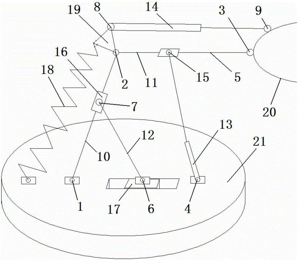
[0017] Controllable mechanism mobile mechanical arm, including rod one 10, rod two 11, rod three 12, telescopic rod one 13, telescopic rod two 14, sliding sleeve one 15, sliding sleeve two 16, slider 17, spring 18, triangular connection plate 19, actuator 20, working platform 21 and trolley,
[0018] The lower end of rod one 10 is connected to the working platform 21 through rotating pair one 1, the upper end of rod one 10 is connected to one end of rod two 11 through rotating pair two 2, and the other end of rod two 11 is connected to the actuator 20 through rotating pair three 3,
[0019] The lower end of the telescopic rod one 13 is connected on the working platform 21 through the rotating pair four 4, the upper end of the telescopic rod one 13 is connected on the sliding sleeve one 15 through the rotating pair five 5, and the sliding sleeve one 15 is sleeved on the rod two 11,
[0020] The lower end of the rod three 12 is connected to the slide block 17 through the rotatin...
PUM
 Abstract
Description
Claims
Application Information