Steel bar splitting-forming and chain transfer machine, section steel stacking device and section steel stacking system

A stacking device and transfer machine technology, applied in the field of section steel stacking, can solve the problems of poor positioning control, affecting stacking quality, increasing investment, etc., achieve stable and reliable equipment operation, improve stacking efficiency, and improve stacking quality Effect

Active Publication Date: 2016-02-17
WISDRI ENG & RES INC LTD
View PDF11 Cites 22 Cited by
  • Summary
  • Abstract
  • Description
  • Claims
  • Application Information

AI Technical Summary

Problems solved by technology

These two methods are labor-intensive, and the stacking quality is poor. For some medium-sized steels, stacking cannot be achieved or the stacking requirements cannot be met at all.
In the later period, the new section steel production line adopted the section steel automatic stacking device successively, but the following problems existed in the use of these section steel automati

Method used


Image

  • Steel bar splitting-forming and chain transfer machine, section steel stacking device and section steel stacking system
  • Steel bar splitting-forming and chain transfer machine, section steel stacking device and section steel stacking system
  • Steel bar splitting-forming and chain transfer machine, section steel stacking device and section steel stacking system

Examples


Embodiment 1

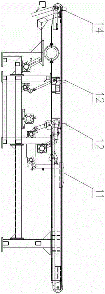
[0027] Such as image 3 , The embodiment of the present invention provides a steel-dividing forming chain transfer machine 4, including a frame, a steel-moving mechanism, a steel-dividing forming mechanism, and a driving mechanism. The frame is a welded structure and is located between the input roller table 1 and the output roller table 10 of the section steel stacking. The steel transfer mechanism includes multiple rows of chain transfer units, and each chain transfer unit is arranged in parallel and at intervals on the frame. The steel-dividing forming mechanism includes a steel-dividing structure and a first positioning structure arranged at intervals on the frame along the steel-moving direction; Arranged in rows between multiple rows of chain transfer units, and at least one row of chain transfer units between two adjacent lifting and separating baffles 11, that is, the direction in which a plurality of lifting and separating baffles 11 are arranged in a row is vertical...

Embodiment 2

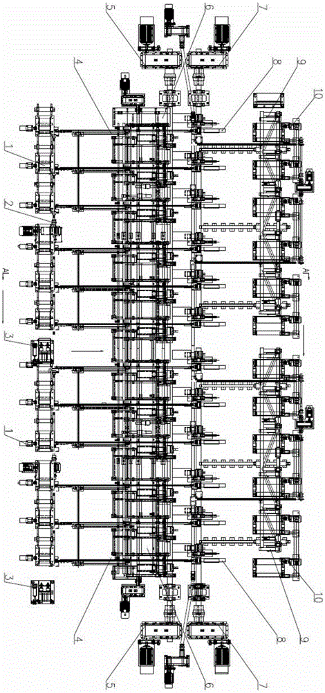
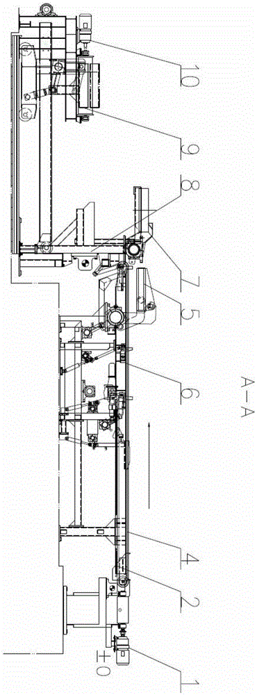
[0035] Such as figure 1 with figure 2 , this embodiment relates to a section steel stacking device, including an input roller table 1, a stacking table 8 and an output roller table 10, and a steel forming chain transfer is set between the input roller table 1 and the stacking table 8 Machine 4, the steel-dividing forming chain transfer machine 4 adopts the steel-dividing forming chain transfer machine 4 provided in Embodiment 1, and will not be repeated here.

[0036] The steel-moving direction of the steel-dividing forming chain transfer machine 4 is perpendicular to the length direction of the input roller table 1; the input roller table 1 and the steel-dividing forming chain transfer machine 4 are connected by a flat trolley 2, and the The steel-dividing forming chain transfer machine 4 is connected with the stacking platform 8 through a stacking mechanism. The pin support trolley 2 is fixed on the roller frame of the input roller table 1 through the bearing seat, and th...

Embodiment 3

[0042] Such as figure 1 , the present embodiment relates to a section steel stacking system, including multiple sets of section steel stacking devices, and the section steel stacking device adopts the section steel stacking device provided in Embodiment 2, which will not be repeated here.

[0043] Such as figure 1 , each of the profiled steel stacking devices is arranged side by side, and a lifting baffle 3 is arranged between the input roller tables 1 of two adjacent profiled steel stacking devices, and along the direction of the profiled steel running of the input roller table 1, the last group of input roller tables 1 The end is equipped with an end alignment mechanism. The end alignment mechanism is a lifting baffle 3 or a fixed baffle.

[0044] In this embodiment, two sets of section steel stacking devices are used; when in use, it is determined whether to use one set of section steel stacking devices for stacking or to use two sets of section steel stacking devices for...


PUM


Abstract

The invention relates to the technical field of section steel stacking, in particular to a steel bar splitting-forming and chain transfer machine, a section bar stacking device adopting the steel bar splitting-forming and chain transfer machine and a section bar stacking system consisting of a plurality of sets of the section bar stacking devices. The steel bar splitting-forming and chain transfer machine is provided with a plurality of groups of baffle plates, so that grouped stacking of section bar products is realized, and misalignment of the section bar products also can be realized. The section bar stacking device adopts a stacking electromagnet to carry out 180-degree turnover stacking on section steel; an turnover electromagnet is additionally arranged for being matched with the stacking electromagnet for carrying out 360-degree turnover stacking on the section steel, so that positive buckling and negative buckling of channel steel and angle steel can be realized; compared with a conventional translation stacking mode, the stacking mode can effectively improve the stacking quality and the stacking efficiency, and equipment operation is stable and reliable, and high in safety. According to specified length of a section steel product, the section steel stacking system adopts one set of section steel stacking devices to carry out stacking, and adopts two sets of section steel stacking devices to carry out combined stacking, so that the stacking efficiency is high and operation is convenient.

Description

technical field [0001] The invention belongs to the technical field of section steel stacking, and in particular relates to a section steel forming chain transfer machine, a section steel stacking device and a section steel stacking system. Background technique [0002] In section steel production, section steel products need to be stacked and collected in bundles. Some production lines in China use manual stacking for the stacking of various shaped steels, and some production lines use mechanical stackers to stack the shaped steels in a fixed slot and then manually bundle them. These two methods are labor-intensive, and the stacking quality is poor. For some medium-sized steels, the stacking cannot be realized or the stacking requirements cannot be met at all. In the later period, the new section steel production line adopted the section steel automatic stacking device successively, but the following problems existed in the use of these section steel automatic stacking dev...

Claims


Application Information

Patent Timeline
IPC IPC(8): B65G57/16
CPCB65G57/16
Inventor 胡于华赖青山罗新华闵威
Owner WISDRI ENG & RES INC LTD
Why Eureka
Try Eureka