Automatic punching machine for bar products

A punching machine and product technology, applied in the direction of driving device, boring/drilling, drilling/drilling equipment, etc., can solve problems such as damage to polygonal bar products

Active Publication Date: 2016-06-01
NINGBO YUNSHENG +1
View PDF7 Cites 4 Cited by
  • Summary
  • Abstract
  • Description
  • Claims
  • Application Information

AI Technical Summary

Problems solved by technology

However, if the bar product is a polygonal bar product, it is necessary to choose a collet with a polygonal cavity at this time. Due to the edges and corners on the outer surface of the polygonal bar product, during the high-speed rotation of the collet, the shape of the collet The cavity cannot be kept at a position that exactly matches the shape of the bar product, and the cavity of the collet will interfere and collide with the outer surface of the polygonal bar product, resulting in damage to the polygonal bar product

Method used


Image

  • Automatic punching machine for bar products
  • Automatic punching machine for bar products

Examples


Embodiment 1

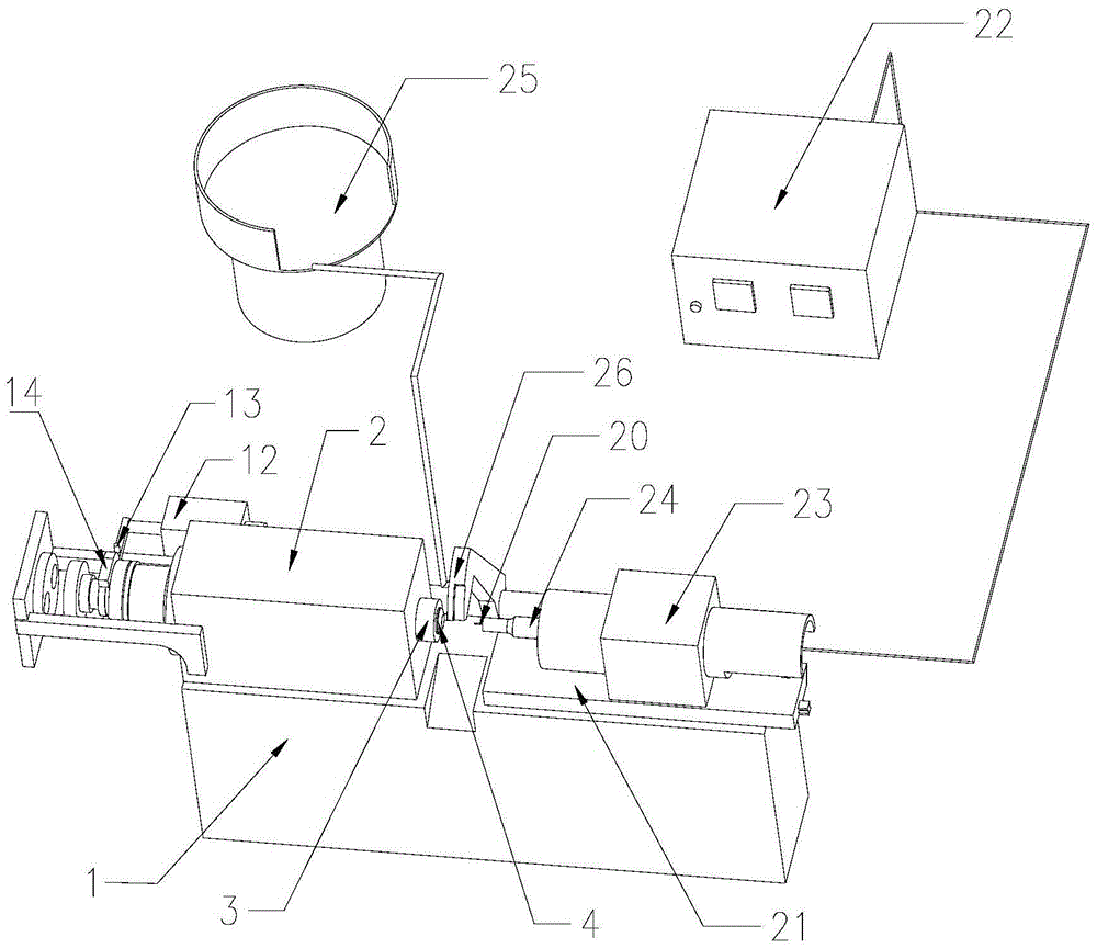
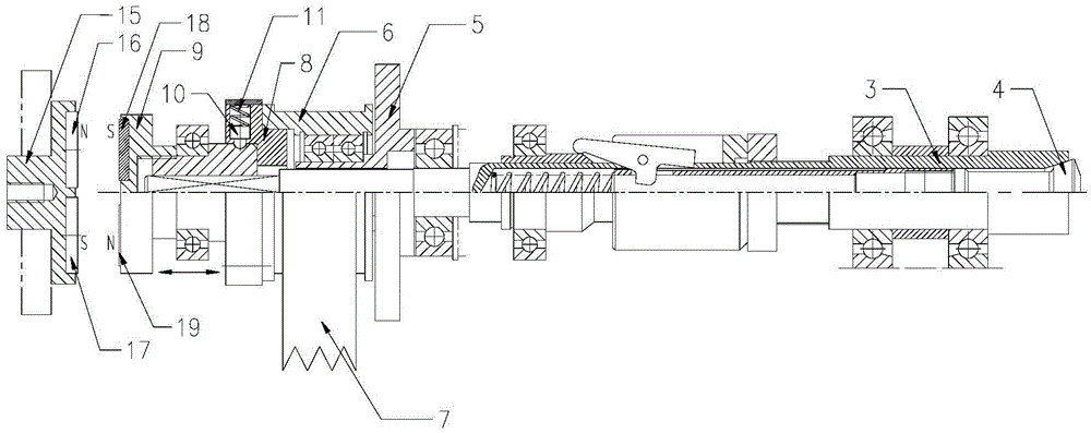
[0017] Embodiment 1: As shown in the figure, an automatic punching machine for bar products includes a frame 1, a controller, a feeding device, a main shaft 3 boxes and a punching device, and the main shaft 3 boxes include a box fixedly arranged on the frame 1 on the box body 2, the main shaft 3, the rotary drive device, the collet 4 and the telescopic drive mechanism, the main shaft 3 is located in the box body 2 and its front end extends out of the box body 2, and the collet chuck 4 is installed in the front end of the main shaft 3 The telescopic drive mechanism is used to drive the collet 4 to extend out of the main shaft 3 or retract into the main shaft 3. The controller is connected with the feeding device, the telescopic drive mechanism and the punching device respectively. The rotary drive device includes a mounting seat 5, a pulley 6, The pulley driving mechanism 7, the first clutch 8, the second clutch 9, the toggle mechanism and the positioning limit mechanism, the to...

Embodiment 2

[0023] Embodiment 2: As shown in the figure, an automatic punching machine for bar products includes a frame 1, a controller, a feeding device, a main shaft 3 boxes and a punching device, and the main shaft 3 boxes include a frame fixed on the frame 1 on the box body 2, the main shaft 3, the rotary drive device, the collet 4 and the telescopic drive mechanism, the main shaft 3 is located in the box body 2 and its front end extends out of the box body 2, and the collet chuck 4 is installed in the front end of the main shaft 3 The telescopic drive mechanism is used to drive the collet 4 to extend out of the main shaft 3 or retract into the main shaft 3. The controller is connected with the feeding device, the telescopic drive mechanism and the punching device respectively. The rotary drive device includes a mounting seat 5, a pulley 6, The pulley driving mechanism 7, the first clutch 8, the second clutch 9, the toggle mechanism and the positioning limit mechanism, the toggle mech...


PUM


Abstract

The invention discloses an automatic punching machine for bar products. The automatic punching machine comprises a rack, a controller, a feeding device, a main shaft box and a punching device; a rotating driving device is constructed by an installation base, a belt wheel, a belt wheel driving mechanism, a first clutch, a second clutch, a stirring mechanism and a positioning limiting mechanism; the stirring mechanism is connected with the controller, the installation base is fixed to a box body, the belt wheel is in shaft connection to the installation base, the first clutch is fixedly connected with the belt wheel, an inner hole is formed in the first clutch, and a locking mechanism is arranged in the first clutch; the second clutch is arranged on the back side of the first clutch and installed at the back end of a main shaft, and the stirring mechanism is used for driving the second clutch to move front and back; and the positioning limiting mechanism is used for stopping rotation of the main shaft after the bar products are punched and enabling a cavity position of a collet chuck to be matched with a containing position of the bar products. The automatic punching machine has the beneficial effect that the automatic punching machine can be used for automatic drilling of round bar products and polygonal bar products at the same time.

Description

technical field [0001] The invention relates to an automatic punching machine, in particular to an automatic punching machine for bar products. Background technique [0002] At present, there are two main types of bar products: round bar products and polygonal bar products. The cross-section of round bar products is circular, and the cross-section of polygonal bar products is polygonal. The existing automatic punching machine for bar products mainly includes a frame, a controller, a feeding device, a spindle box and a punching device; Rotary rotary drive device, collet and telescopic drive mechanism, the main shaft is located in the box and its front end protrudes out of the box, the collet is installed in the front end of the main shaft, the collet has a cavity that matches the bar product, The telescopic drive mechanism is used to drive the collet to extend out of the main shaft to open or retract to close the main shaft. The controller is respectively connected with the...

Claims


Application Information

Patent Timeline
Patent Type & Authority Applications(China)
IPC IPC(8): B23B41/00B23B47/00B23B47/04
CPCB23B41/00B23B47/00B23Q5/04
Inventor 陈华沈其昌郑卿
Owner NINGBO YUNSHENG
Why Eureka
Try Eureka