
A paper receiving and pulling device and its working method

A technology of paper-pushing device and working method, which is applied in the direction of transportation and packaging, sending objects, and thin material processing, etc., which can solve the problems of poor paper collection, chaotic paper shutdown, and unsmooth movement, etc., and achieves a compact mechanical structure and a reasonable space. , the effect of reasonable layout

Active Publication Date: 2018-01-16
MASTERWORK GROUP CO LTD
View PDF7 Cites 0 Cited by
  • Summary
  • Abstract
  • Description
  • Claims
  • Application Information

AI Technical Summary

Problems solved by technology

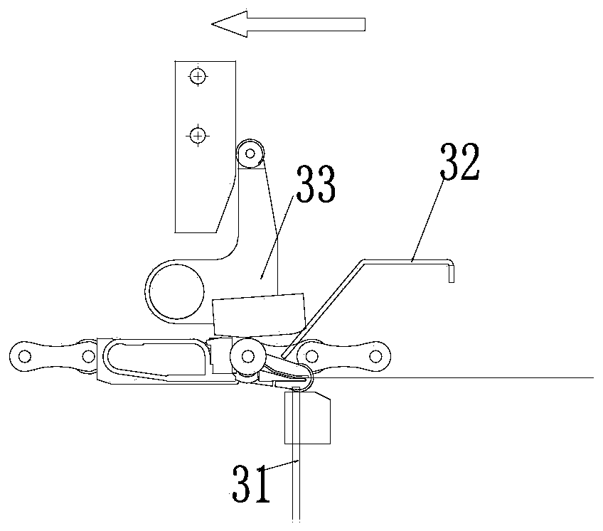
[0004] This technical solution mainly has the following disadvantages: when the equipment is running at high speed, the front end of the paper is caught by the tooth row and stops slowly with the tooth row, but the rear end of the paper will continue to impact towards the front due to the effect of inertia, resulting in paper in the carton The connection point between them is broken, which is not conducive to the collection of paper. At the same time, when the paper stops with the tooth row, before the tooth row opens the teeth, the front end of the paper is held by the tooth row, and the rear end hangs freely. When the row is pulled out, the paper will have a backward movement. Since the rear end of the paper has fallen on the collecting platform, and some connection points between the paper boxes have been broken, it will cause the backward movement of the paper to be unsmooth. This will further aggravate the breakage of the connection point of the carton, resulting in the unsmooth falling of the paper, which will easily cause poor paper collection, or the paper will be messed up here and the machine will stop

Method used

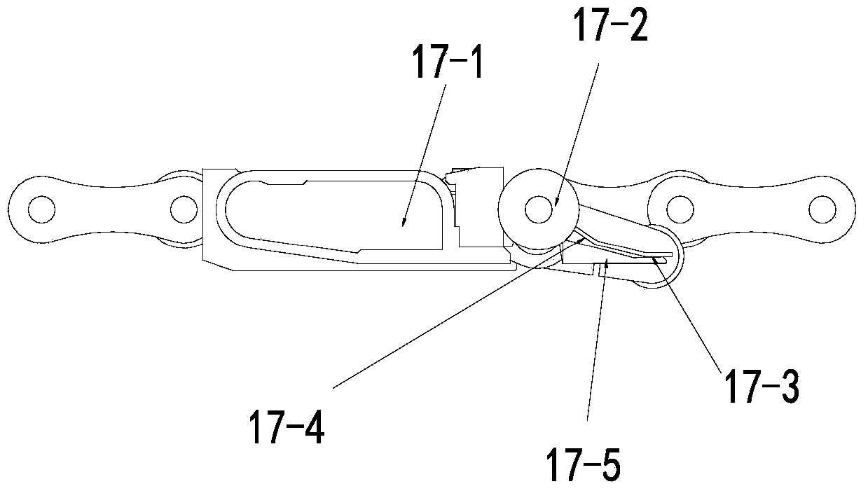

Image

  • A paper receiving and pulling device and its working method
  • A paper receiving and pulling device and its working method
  • A paper receiving and pulling device and its working method

Examples


Embodiment

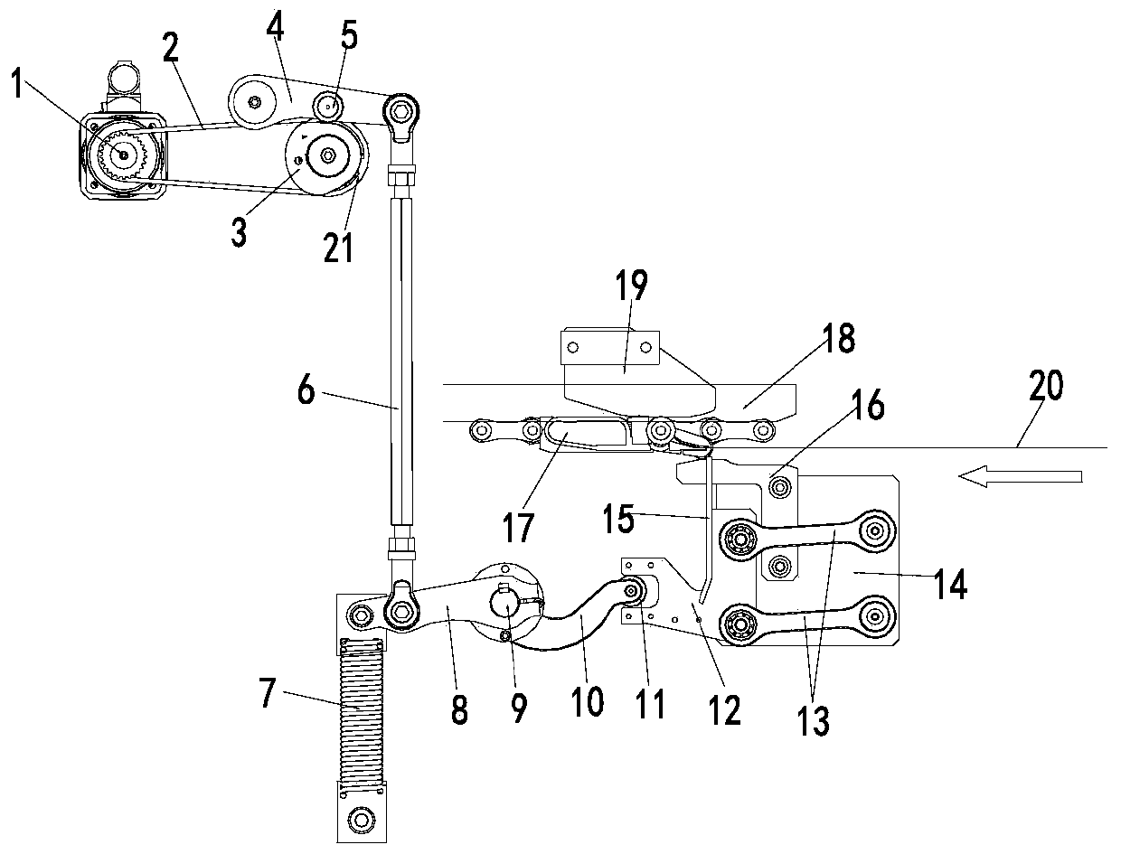
[0031] Embodiment: a kind of paper receiving and pulling device (see image 3 ), including the row of teeth 17, characterized in that it also includes a drive unit, connecting plate 12, connecting rod III13, fixed plate 14, paper blocking plate 15 and tooth opening block 16; the drive unit is connected with the connecting plate 12; The swing end of the connecting rod III13 is hingedly connected to the connecting plate 12, and the fixed end of the connecting rod III13 is hingedly connected to the fixing plate 14; the paper blocking plate 15 is fixed on the connecting plate 12, and the opening block 16 is fixed on the fixing plate 14; The connecting plate 12, the connecting rod III 13 and the fixed plate 14 form a four-bar linkage.

[0032] The connecting plate 12 can swing up and down with the fixed end of the connecting rod III13 as the axis. (See image 3 )

[0033] The drive unit is mated with the connecting plate 12 through the transmission unit. (See image 3 )

[00...


PUM


Abstract

A paper receiving and pulling device, including a driving unit, a connecting plate, a connecting rod III, a fixed plate, a paper stopper and a tooth opening block; the driving unit is connected with the connecting plate; the swing end of the connecting rod III is connected to the connecting plate Hinged connection, the fixed end of the connecting rod III is hinged with the fixed plate; the cardboard is fixed on the connecting plate, and the opening block is fixed on the fixing plate to correspond to the opening ball of the tooth row; the connecting plate, connecting rod III 1. The fixed plate constitutes a four-bar linkage mechanism; the connecting plate can swing up and down with the fixed end of the connecting rod III as the axis. Working method: After the cardboard is higher than the upper tooth piece of the tooth row, the tooth row is opened under the action of the tooth block, and the loosened paper is blocked by the cardboard; the tooth row continues to move forward, so that the paper stopper completely blocks the paper After the tooth row, the paper naturally falls to the collecting platform. Advantages: The paper is completely separated from the tooth row during the operation, the paper is flat when separated, and then the paper falls to the collecting platform smoothly, and the collected paper is more flat.

Description

(1) Technical field: [0001] The invention is suitable for printing machinery, especially for die-cutting equipment with a finishing unit, and belongs to a paper receiving and pulling device and a working method thereof. (two) background technology: [0002] The single-fed waste stripping die-cutting equipment uses the tooth row to make the paper circulate in each process station. After the die-cutting action is completed, the tooth row is opened in the finished product cleaning unit, and the paper is smoothly dropped after the paper is pulled, and the paper falls on the collection unit below. After being collected into stacks, it is transported to the outside of the equipment through the logistics system. [0003] In order to realize the function of collecting paper in the finished product unit, the paper receiving and pulling device of the prior art is as figure 1 As shown, it is mainly composed of three parts: a fixed baffle 31 arranged at the mouth of the mouth, a cardbo...

Claims


Application Information

Patent Timeline
Patent Type & Authority Patents(China)
IPC IPC(8): B65H29/36
Inventor 韦树远刘东
Owner MASTERWORK GROUP CO LTD
Learn More