[0061] In order to better illustrate the purpose and advantages of the present invention, the content of the present invention will be further described below with reference to the accompanying drawings and examples.
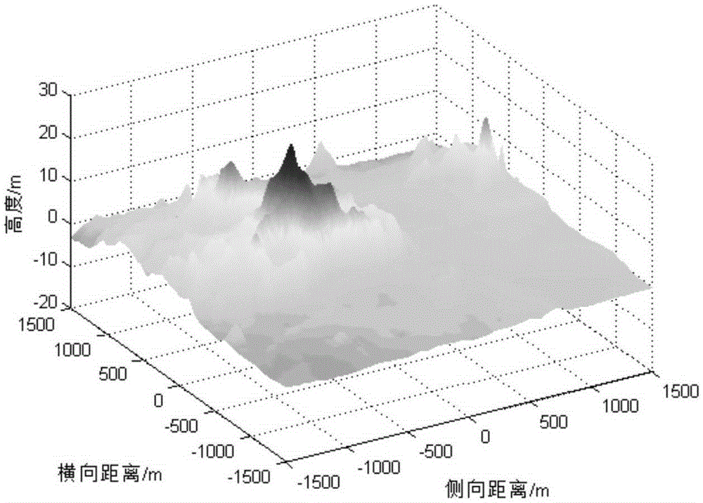
[0062] In this example, the thrust engine specific impulse I sp Is 225s, the mass of the probe is 1905kg, the maximum speed increment ΔV is 190m/s, the landing time Δt is 35s, the initial position r 0 Is [-300,-200,1700]m, the initial velocity v 0 It is [18,20,-80]m/s, and the negative sign means the direction is vertically downward. The terrain used in the simulation is shown in Figure 3.
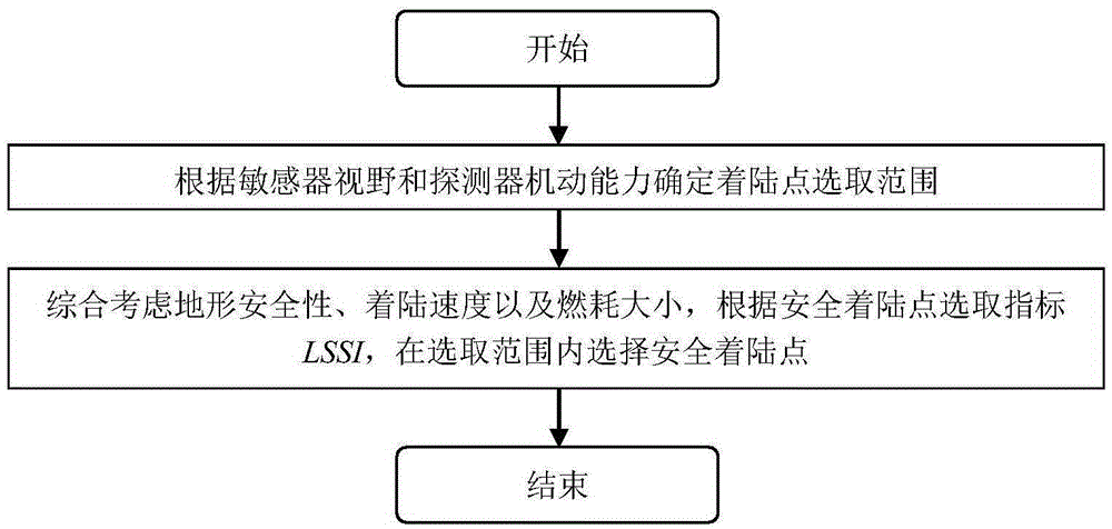
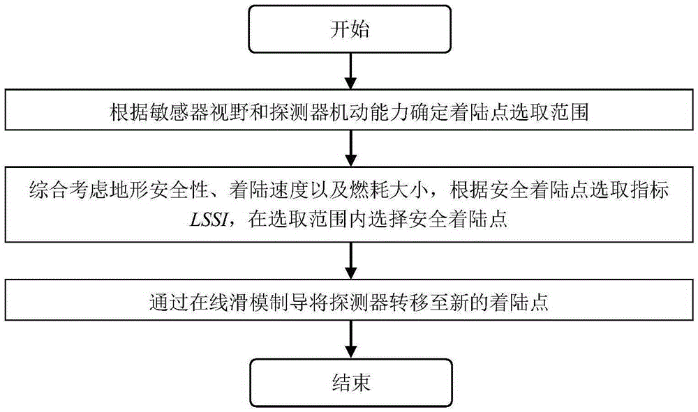
[0063] This embodiment discloses a planetary safe landing guidance method for online selection of landing points, including the following steps:
[0064] Step 1: Determine the selection range of a safe landing point. After the maneuverability boundary is obtained, take the intersection of the area covered by the maneuverability and the field of view of the sensor, and use this intersection as the selection range of the safe landing point for the landing point selection in step 2.
[0065] Given the dynamics of the descending stage, after weighing the pixel resolution and the overlap of the image, a camera with a 45-degree field of view is selected. Without considering the attitude of the detector, it is assumed that the camera is parallel to the horizontal plane and the ground is photographed. The dynamic descending stage The initial height is 1700m, and this height is used as the shooting and calculation height. The initial position of the detector r 0 , Initial velocity v 0 , The maximum velocity increment ΔV, the detector energy E, the detector mass m, and the landing time Δt are substituted into formula (2) to obtain the semi-major axis a of the burnup ellipse = 1537.4m, and the semi-minor axis b = 1521.9m. The XY plane draws the range of maneuverability of the detector. MATLAB simulation results such as Figure 4 As shown, the solid gray line is the original landing track of the detector, the solid rectangle on the XY plane is the camera field of view, and the dashed ellipse is the range of the detector's maneuverability. Under the given initial conditions, the maneuverability of the detector completely includes the camera's field of view. Therefore, the final landing point can be obtained only by using the safe landing point selection method within the field of view.
[0066] Step 2: Obtain terrain safety, landing speed and fuel consumption information online in real time, and use the formula (3) that comprehensively considers terrain safety, landing speed and fuel consumption to select a safe landing site.
[0067] When considering terrain safety, landing deviation r f Set it as 50m, and the terrain safety evaluation index parameter c=50. Perform obstacle analysis on the terrain given in Figure 3 and calculate the safety radius R of each point in the selected range. Substitute the result into formula (4) to get the terrain of each point Safety Evaluation Index I t. When analyzing the landing speed of the probe, a 5% execution error and a wind model that obey the Weibull distribution were added, and the final landing speed v at each point was calculated through the sliding mode guidance law. fz. Similarly, the sliding mode guidance law and formula (5) are used to calculate the fuel mass ratio PMF that reaches each point in the selected range. The calculation results of terrain safety, landing speed and fuel consumption index are normalized by min-max, and the results are as follows Figure 5a , 5b , As shown in 5c. Calculate the weight according to the weighting method given in formula (7) to obtain τ=[1,0.5789,0.4211], and substitute the result into formula (6) to obtain Figure 5d The value of the safe landing point selection index LSSI in the entire field of view is shown. The position coordinates of the safe landing point are calculated as [1166,-1389,0], and the value of the selected index LSSI at this point is the global minimum Is 0.3558.
[0068] Step 3: Transfer the probe to the new landing site through the online sliding mode guidance law. Because the sliding mode guidance method has better robustness, the use of sliding mode guidance method can effectively solve the external interference and unmodeled errors during the landing process, and improve the safety and reliability of the mission.
[0069] After the guidance control system has updated the terminal state, that is, the landing point coordinates [1166,-1389,0], it can generate the landing trajectory online according to the sliding mode guidance law formula (16), and transfer the detector to a new safe landing point. In order to verify the sliding mode guidance method for the initial position r 0 And initial velocity v 0 The robustness of 1000 times Monte Carlo simulation, assuming the initial position r 0 And initial velocity v 0 Obey the Gaussian distribution, the simulation results are as Figure 6a-6f. Within a given range of change, the detector can reach the designated landing site with almost zero position and speed error within a limited time, and during the entire landing process, there is no case of falling below the ground, indicating the sliding mode guidance For initial position r 0 And initial velocity v 0 The deviation has good robustness, can realize the online update of the landing point and can better transfer the detector to the target landing point.
[0070] The protection scope of the present invention is not limited to the embodiments. The embodiments are used to explain the present invention. Any changes or modifications under the same principle and concept as the present invention are within the protection scope disclosed by the present invention.