
Self-circulation energy storage power generation device

A power generation device and energy storage technology, which is applied in the direction of electromechanical devices, electrical components, electric components, etc., can solve problems such as uninterrupted power supply, and achieve the effects of overcoming mechanical friction, overcoming mechanical resistance, and reducing mechanical friction

Inactive Publication Date: 2016-02-17
刘国斌 +1
View PDF0 Cites 2 Cited by
  • Summary
  • Abstract
  • Description
  • Claims
  • Application Information

AI Technical Summary

Problems solved by technology

[0003] The purpose of the present invention is to solve the problems in the prior art that cannot be charged and discharged at the same time and cannot provide uninterrupted power supply, so as to provide a "self-cir

Method used


Image

  • Self-circulation energy storage power generation device
  • Self-circulation energy storage power generation device
  • Self-circulation energy storage power generation device

Examples


Embodiment Construction

[0025] specific implementation plan

[0026] In order to make the purpose, technical solution and advantages of the present invention clearer and clearer, the following will be further described with reference to the accompanying drawings and examples:

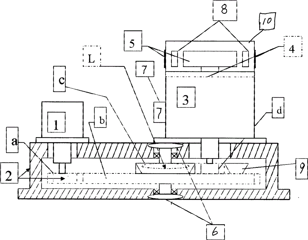
[0027] figure 1 What is shown is the schematic diagram of the "energy storage power generation device";

[0028] Described energy storage power generation device---by starter motor 1, gear amplifying mechanism 2, kinetic energy storage mechanism 3, magnetic bearing 46), flywheel 5, vacuum pump 7, buffer wheel 8, positioning bevel gear 9, vacuum cover 10, Clutch L and abcd four gears and other components):

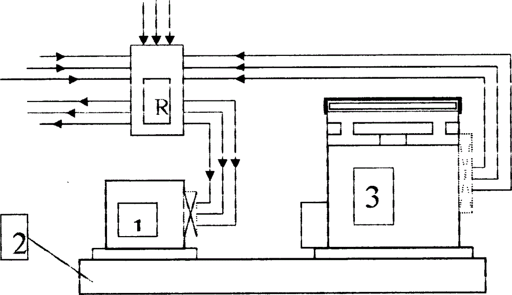
[0029] figure 2 A schematic diagram of the assembly of the "Energy Storage and Power Generation Device" at work is provided:

[0030] Such as figure 2 Shown: The starting motor 1 of the "energy storage power generation device" through the "electric power and electronic control system R" - after the external power sup...


PUM


Abstract

The invention discloses a self-circulation energy storage power generation device which comprises an energy storage power generation device and a power and electronic conversion control system, wherein the energy storage power generation device comprises a kinetic energy amplification device and a kinetic energy storage mechanism, and the device is designed according to a lever principle and a flywheel effect theory. By the device, input power can be effectively amplified; under the coordination of a flywheel effect, output energy in an isolated system can be greater than input energy by the device, and thus, the purpose of directly converting earth gravity into power also can be achieved.

Description

technical field [0001] The present invention relates to an energy storage power generation device, in particular to a self-circulation energy storage power generation device; Background technique [0002] Now there are many introductions about flywheel batteries on the Internet. The batteries are composed of flywheels, flywheel shafts, magnetic bearings, permanent magnet motors, fuselages and vacuum covers. Their advantages are large storage capacity, long service life and environmental protection; but Their disadvantage is that they cannot be charged when they are powered, they cannot be powered when they are charged, and they cannot be powered continuously, so they can only be used purely as batteries; Contents of the invention [0003] The purpose of the present invention is to solve the problems in the prior art that cannot be charged and discharged at the same time and cannot provide uninterrupted power supply, so as to provide a "self-circulation energy storage power...

Claims


Application Information

Patent Timeline
IPC IPC(8): H02K53/00H02K7/02H02K7/118
CPCY02E60/16
Inventor 刘国斌刘光远
Owner 刘国斌
Learn More