
Information presenting device

a technology of information presenting and presenting device, which is applied in the direction of machine supports, household objects, applications, etc., can solve the problems of occupying a large amount of space, not particularly attractive to look, and the need to fit the tensioning elemen

Inactive Publication Date: 2011-07-28
MIZELDA
View PDF11 Cites 15 Cited by
  • Summary
  • Abstract
  • Description
  • Claims
  • Application Information

AI Technical Summary

Benefits of technology

[0013]One object of the present invention is to provide an information presenting device which is easy to extend from a first, flattened configuration into a second, extended configuration.
[0014]One more object of the present invention is to provide an information presenting device which is easy to recycle.
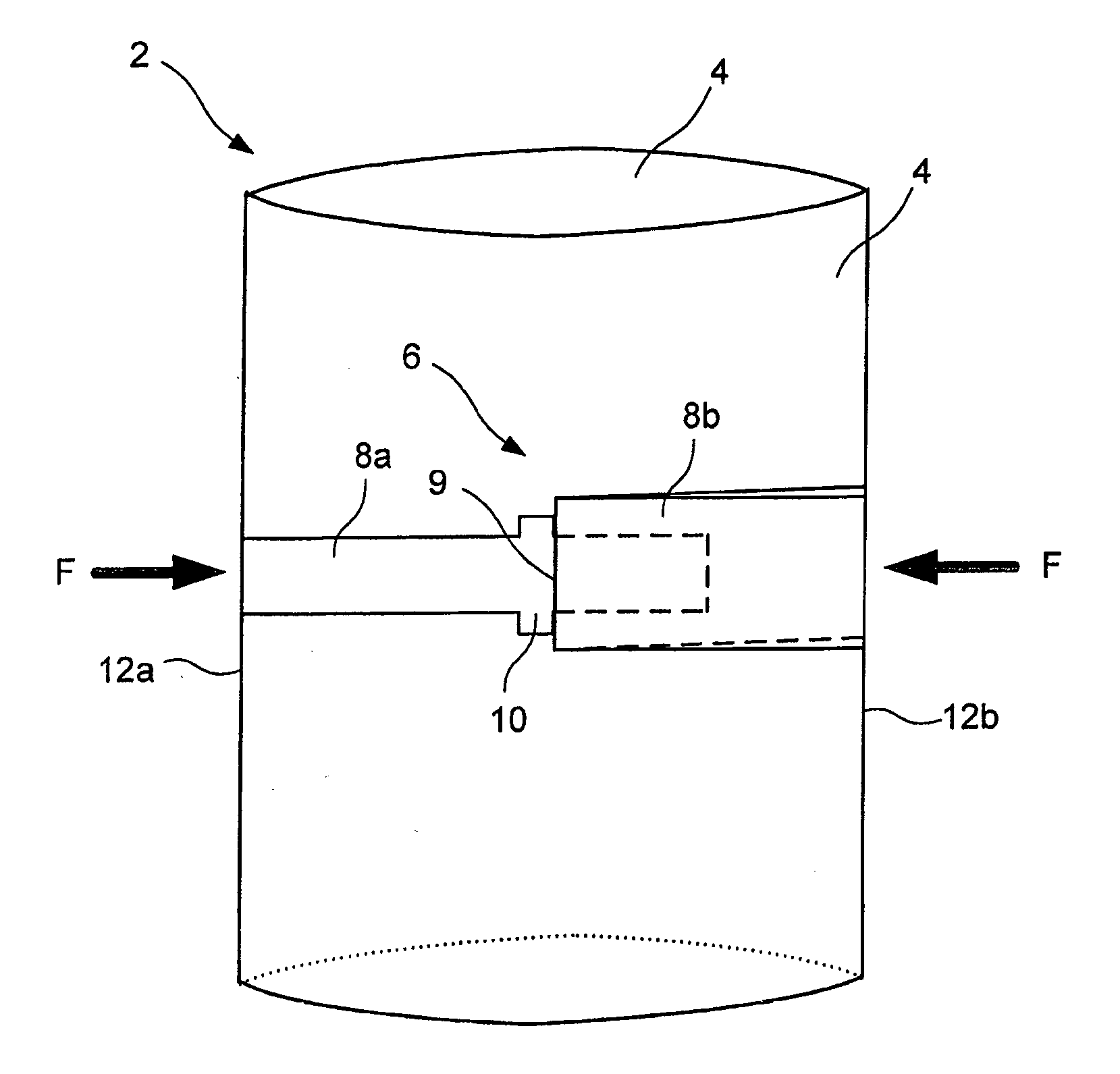
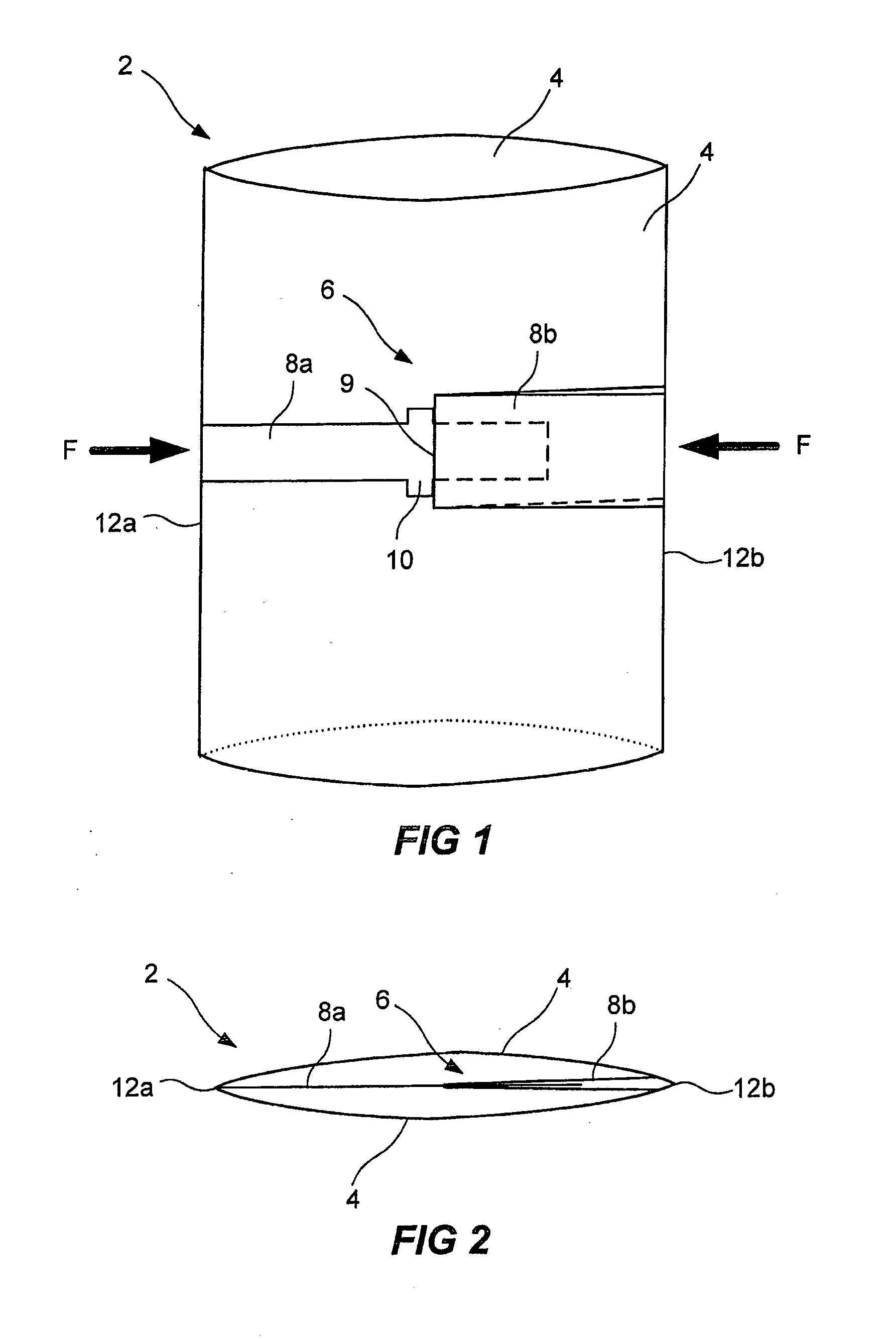
[0016]A device has thus been provided which is easy to extend. Furthermore, the device is also easy to flatten following extension. This since the locking member acts to lock the device in both said first and said second configuration. This locking is realized automatically as long as the friction of the friction band coupling between the contact surfaces of the first part and the second part of the locking member is not overcome. The fact that the first part of the locking member is slidably connected to the second part of the locking member together with the fact that the locking of the device is continuously adjustable means that the device can assume all conceivable configurations between the two extremes to which the first, flattened configuration and the second, extended configuration correspond. The sliding connection between the first and second part of the locking member is continuously adjustable, i.e. stepless. In one or other of the two configurations (or some configuration therebetween), the device is in its state of rest, i.e. in order to alter the configuration of the device, a force which overcomes the friction of the friction band coupling between said first and second part of the locking member must be overcome. The rigidity of the panels, together with the cylindrical configuration of the device, results in the device, in its extended, second configuration, being self-supporting. A device of said type is simple to produce and assemble, which makes the production relatively cheap.
[0017]The locking member can be made of similar material to said at least two panels. By similar material is meant, for example, paper fibers. By producing all the parts of the device in similar material, recycling of the device is made considerably easier. Upon disposal, the various parts of the device do not need to be separated from one another, but rather it is possible to throw away the whole device as, for example, cardboard, if the device is now made of paper fibers. It will be appreciated, however, that other materials can also be used, for example the whole of the device can be produced in plastics material.
[0018]A portion of the first part of the locking member can be inserted in a first recess in the second part of the locking member. In this way, a large contact surface between the first and second part of the locking member can be achieved and thus a reliable friction band coupling is achieved. A large contact surface gives rise to the necessary friction between the parts of the locking member.
[0019]The first part of the locking member can be formed by a tongue. The second part of the locking member can be formed by a doubled-over strip. A tongue which is inserted into a doubled-over strip can generate the necessary friction in order to form the friction band coupling in a simple manner.

Problems solved by technology

The use of posters or the like has drawbacks, such as that the posters have to be hung up on something and are not particularly attractive to look at.
A drawback with the transport and storage of advertising pillars is that they occupy a large amount of space.
A drawback with both these solutions is that a tensioning element needs to be fitted to the advertising pillar, or alternatively a supporting member needs to be hooked together in order to maintain the extended configuration.
Both of these solutions are cumbersome for the user, since the user must actively fit the tensioning element, or alternatively must actively hook together a supporting member.
One drawback with the above-described, automatically extended advertising pillars is precisely the automatic extension.
Another drawback is that the tensioning elements (for example the elastic bands) are made of rubber or some other elastic material, thereby making the advertising pillar more difficult to recycle.
Yet another drawback is that the tensioning elements age, which causes the possible storage time for the advertising pillars to be shortened.

Method used


Image

  • Information presenting device
  • Information presenting device
  • Information presenting device

Examples


Embodiment Construction

[0036]In FIGS. 1 and 2, an embodiment of the information presenting device 2 according to the invention is illustrated. The embodiment is shown in its second configuration, in which the device 2 is extended and hence self-supporting. The device 2 is also arranged to assume a first configuration, in which the device 2 is flattened for transport or storage, see FIGS. 4 and 5 and the description below.

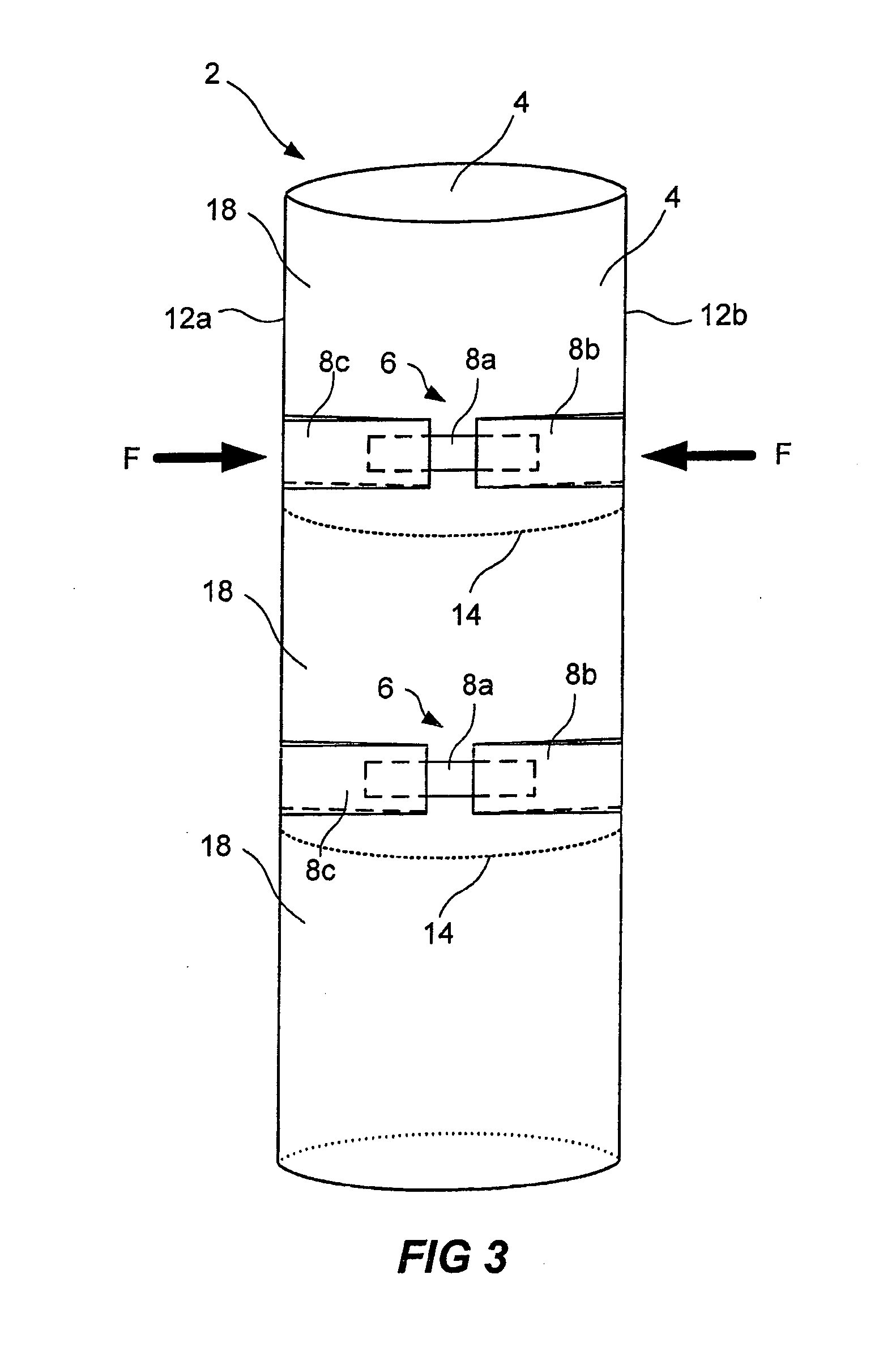
[0037]That embodiment of the device 2 which is shown in FIGS. 1 and 2 comprises two panels 4. It will be appreciated that the device 2 can comprise more than two panels. Examples of embodiments having more than two panels are discussed below with reference to FIGS. 6a and 6b. The panels are made of a rigid, yet flexible material. For example, the material can be corrugated board or box board. The rigidity makes the device self-supporting in its extended, second configuration. The flexibility allows the panels to be bent and thus assume a convex shape, like the embodiment shown in FIGS. 1 ...


PUM

PropertyMeasurementUnit
Flexibilityaaaaaaaaaa

Abstract

An information presenting device. The device is arranged to be capable of assuming a first configuration, in which the device is flattened for transport or storage, and of assuming a second configuration, in which the device is extended and hence self-supporting. The device comprises at least two panels 4, made of a rigid material, which are joined together along the respective edges of at least two of the panels such that the device, having assumed the second configuration, forms a hollow cylinder, and at least one locking member 6, arranged between said panels 4, for continuously adjustable locking of the device in said first or second configuration, the locking member 6 comprising a first part 8a and a second part 8b, the first part 8a being slidably connected to the second part 8b and the locking member 6 being self-locking by a friction band coupling formed between contact surfaces of the first part 8a and the second part 8b of the locking member 6.

Description

TECHNICAL FIELD[0001]The present invention relates to an information presenting device, which device is arranged to be capable of assuming a first configuration, in which the device is flattened for transport or storage, and of assuming a second configuration, in which the device is extended and hence self-supporting. The invention further relates to a method for extending a device according to the above from the first, flattened configuration into the second, extended configuration.BACKGROUND ART[0002]The presentation of information such as notices or advertising at sales outlets, so-called shop advertising, is nowadays common practice. A common way of presenting the information is by means of posters of different kinds. The use of posters or the like has drawbacks, such as that the posters have to be hung up on something and are not particularly attractive to look at. Advertising by means of self-supporting advertising pillars has therefore become increasingly common. A drawback w...

Claims


Application Information

Patent Timeline
IPC IPC(8): G09F15/02G09F15/00G09F1/06B23P17/04
CPCG09F1/065Y10T29/49716G09F15/0025G09F1/06G09F15/0062
Inventor MIRSCH, JANI
Owner MIZELDA
Learn More