
Inflow control valve for controlling the flow of fluids into a generally horizontal production well and method of using the same

a technology of inflow control valve and production well, which is applied in the field of in situ hydrocarbon extraction, can solve the problems of unsatisfactory gas loss into the production well, unsatisfactory recompression and re-injection, and the loss of gas into the production well is undesirable, and achieves the effect of reliably opening and closing

Active Publication Date: 2016-07-19
NENNIGER JOHN
View PDF6 Cites 14 Cited by
  • Summary
  • Abstract
  • Description
  • Claims
  • Application Information

AI Technical Summary

Benefits of technology

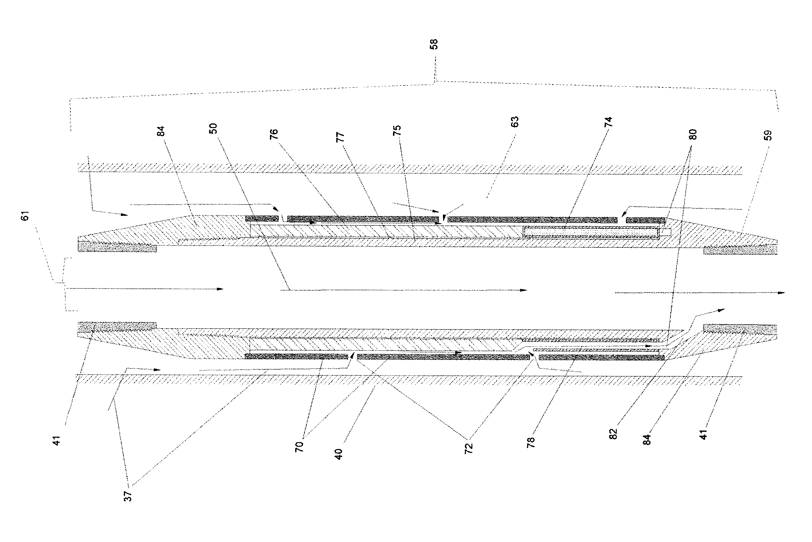
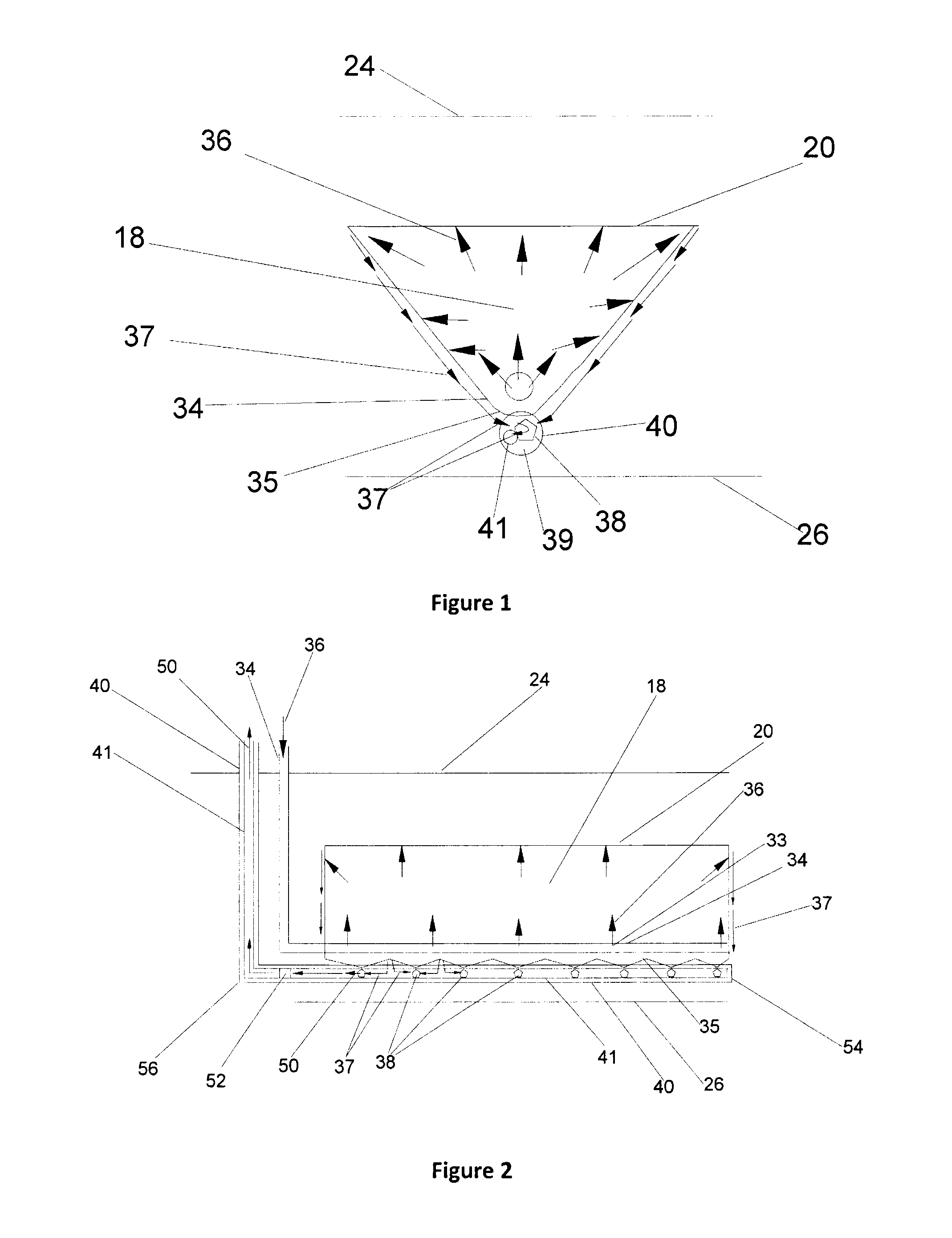
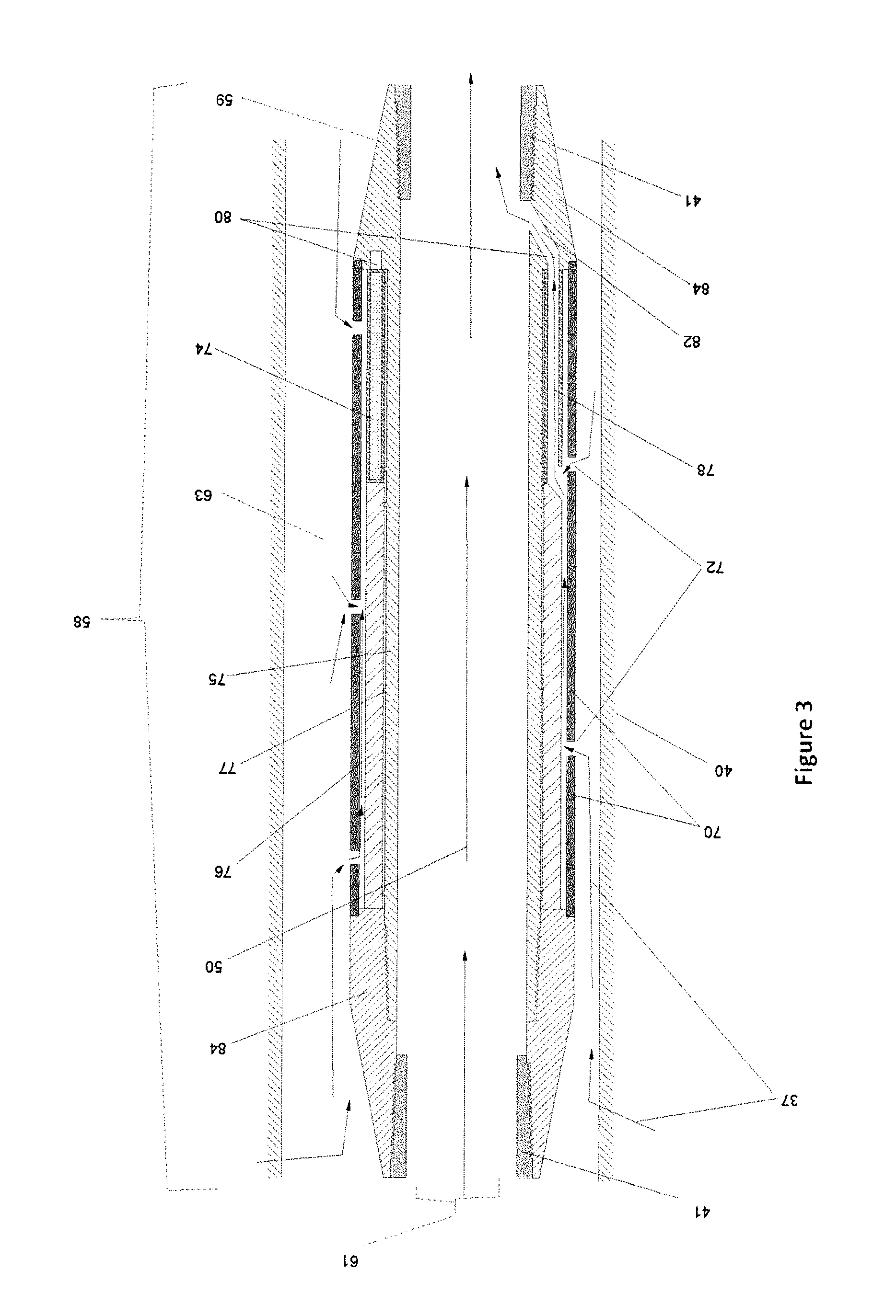
[0019]The present invention comprehends a method and apparatus comprising an inflow control valve which opens or closes to allow liquid flow into the production well but restricts vapour production or loss from the vapour chamber to the production tubing. More generally, what is comprehended is a valve to enable operators to apply substantive pressure drawdown while still maintaining adequate liquid submergence, because the pressure drawdown does not affect the performance of the inflow control device. In other words the present invention is intended to provide a design that can open and close reliably despite being subjected to a dynamic (highly variable) pressure drawdown.
[0020]The present invention further presents an apparatus is intended to respond appropriately to bubble point fluids, which are prone to flashing by being able to open and close to in response to changes in liquid submergence rather than to a pressure drop across the valve. As well the design is relatively simple and efficient. The present invention further provides a design that moves in position as required to produce an effective amount of torque from a starting position, and is not metastable and thus can reliably overcome inevitable friction and viscous resistance to provide rapid and reliable opening and closing actuation.
[0021]According to the present invention the inflow control device can be deployed at numerous locations along the production tubing in a horizontal well. According to a further aspect of the present design better inflow control permits the horizontal wells to be extended in length to thereby reduce surface environmental footprint as well as achieve greater economies of scale. Further the present invention is intended to provide an apparatus and / or method that enables a more efficient use of steam, water and fuel energy and reduces GHG emissions as compared to the prior art. Further, better drainage will enable thinner pay zones to be effectively recovered. Better drainage control will enable better recovery of more challenging in situ conditions such as ones that may be wetter and leaner than is ideal.
[0023]The present invention comprehends that such inflow control valves can be easily installed along the production tubing through conventional well tool installation techniques. Any number of these valves can be placed along the extended horizontal wellbore to provide optimized local drainage for individual or short sections of the horizontal production well and thereby keep the liquid sump in the gravity drainage chamber at a desired minimum amount. At the same time the present invention is intended to prevent steam break through to the production tubing even in the presence of a significant drawdown pressure.
[0032]injecting a vapour into an underground formation above said production well to reduce a viscosity of in situ hydrocarbons sufficiently so that the hydrocarbons can drain as a liquid towards and into said production well; and
[0033]permitting liquid to pass through said inflow control valve when said annulus is at least partially full of said liquid and thereby preventing vapour from passing into said production tubing.

Problems solved by technology

Any vapour that passes into the production well represents a loss of efficiency for the extraction process because it is unable to deliver its latent heat and / or its solvent content to the oil to be recovered.
Even in the case of gas assisted gravity drainage, where an inert gas is injected into the vapour chamber without any intention of mobilizing the oil but simply to help fill the voidage volume in the extraction chamber, the loss of gas into the production well is undesirable.
Typically any such vented gas must be separated at surface from the produced fluids, dried, recompressed and re-injected at considerable cost.
This steam trap control should reduce the use of steam as compared to say a cyclic steam extraction (so called “huff and puff”) because live steam is unavoidably vented during the “puff” production phase of the latter process thereby greatly reducing the thermal efficiency of the extraction.
But this has not proved to be the case.
Maintaining the liquid submergence by controlling the fluid withdrawal rate is very challenging.
If the liquid drainage at the rate at a particular location along the horizontal production well is too slow, the fluid level at that location can rise and even submerge the vapour injection well.
In SAGD, locations that are flooded cannot be effectively heated by the injected steam, leading to a risk of having the bitumen cool down in that local area, become too viscous to drain, and thereby render portions of the horizontal well less productive or even completely unproductive.
This is very undesirable because the steam heating may become focused on the cap rock at the top of the pay zone which is unproductive, and fluid drainage to the production well may be limited to a few “chimneys”.
Further this misplaced heating may allow the production well to cool off so much that produced fluids in the liquid sump become too viscous to flow without excessive pressure drive.
Unfortunately, aggressive drawdown pressures also inevitably leads to steam vapour breakthrough at one or more locations along the length of the horizontal well and direct production of steam through the production well.
Direct production of steam leads to high energy consumption and excess greenhouse gas production both of which are expensive and highly undesirable as outlined below.
However, this design has several problems that make it unsuitable for SAGD applications or any other processes that operate close to bubble point conditions as set out below.
A first problem is that in some embodiments the moveable valve is designed in a way that permits it to be actuated by pressure drawdown.
This would permit vapour to escape by reason of drawdown pressure, which is the exact problem that operators currently face.
A second problem is that the flow restriction element may be located downstream of a flow passageway from the annulus.
This downstream position renders the design unsuitable for SAGD because a small reduction in pressure within the production tubing can lead to substantive flashing of bubble point liquid into the vapour phase.
Eventually, if exposed to water, it would close, but in a dirty and viscous environment, such as normally found in SAGD production (with high viscosity bitumen and grit or sand), the meta-stable design will be slow to overcome the unavoidable and inevitable friction.
A final problem is that the valve taught aligns itself with a predetermined orientation upon being positioned within the well bore, and then may be sealed to the casing, for example, with expanding seals.
These and other limitations that will be apparent to those skilled in the art mean that this prior art device is of limited, if any, use in gravity drainage processes.
A problem with a device which responds to pressure drop is that the pressure drop is not necessarily related to liquid levels in the sump around the production well.

Method used


Image

  • Inflow control valve for controlling the flow of fluids into a generally horizontal production well and method of using the same
  • Inflow control valve for controlling the flow of fluids into a generally horizontal production well and method of using the same
  • Inflow control valve for controlling the flow of fluids into a generally horizontal production well and method of using the same

Examples


Embodiment Construction

[0052]In this description the following terms shall be understood to have the following meanings. The terms vertical and horizontal are meant to indicate generally vertical or horizontal. For example, it is common to refer to a horizontal production well that may not in practice be straight or perfectly horizontal, but is generally more horizontal than vertical. The same applies to the term vertical, which in this case means more vertical than horizontal. The term “riser” means that portion of the wellbore or production tubing that extends from the underground reservoir to the surface to transport the production fluids. Many well configurations and drill patterns can be used and the precise shape and slope of production wells and risers can vary considerably without departing from the scope of the present invention. In this specification the term fluids shall comprehend both liquids and gases and combinations thereof. In some cases the fluids will also contain mixtures of two differ...


PUM


Abstract

An inflow control valve has a valve body having a threaded portion for connecting the valve body to a production tubing, a through bore for connecting the valve body to an inside bore of the production tubing and an outside surface; at least one inlet passageway extending through the valve body between the outside surface and the through bore and an inlet opening on the at least one inlet passageway formed on the outside surface of the valve body; a closure member for opening and closing the inlet opening, the closure member being located between the inlet opening and the annulus; and a member to bias the closure member to an open position when the inlet opening is submerged in a liquid to be recovered from the reservoir and to bias the closure member to a closed position in the absence of the liquid at the inlet opening.

Description

FIELD OF THE INVENTION[0001]This invention relates to the field of in situ hydrocarbon extraction and more particularly to the extraction of conventional oil, heavy oil and bitumen from underground formations using extraction processes which use generally horizontal production wells. Most particularly this invention relates to methods and apparatuses to control the inflow of fluids into the horizontal production well to improve the overall thermal efficiency of the production of hydrocarbons from such horizontal wells.BACKGROUND OF THE INVENTION[0002]Horizontal wells are now used extensively in the production of hydrocarbons from underground formations or reservoirs. Gravity drainage is an emerging technique that uses horizontal wells and it promises to greatly increase the economically recoverable reserves of oil. In a gravity drainage process, a typical well configuration involves paired horizontal wells: one for vapour injection; and a second one for liquid production. An extract...

Claims


Application Information

Patent Timeline
Patent Type & Authority Patents(United States)
IPC IPC(8): E21B43/12E21B43/24E21B43/16E21B34/08E21B43/30
CPCE21B43/12E21B34/08E21B43/166E21B43/2406E21B43/305
Inventor NENNIGER, JOHN
Owner NENNIGER JOHN
Learn More