Multi-terminal linkage method and system, and associated equipment
A multi-terminal and client-side technology, applied in transmission systems, digital transmission systems, electrical components, etc., can solve problems such as poor multi-terminal linkage linkage effects, achieve the effect of improving switching smoothness and continuity, and improving linkage effects
- Summary
- Abstract
- Description
- Claims
- Application Information
AI Technical Summary
Problems solved by technology
Method used
Image

Examples
Embodiment 1
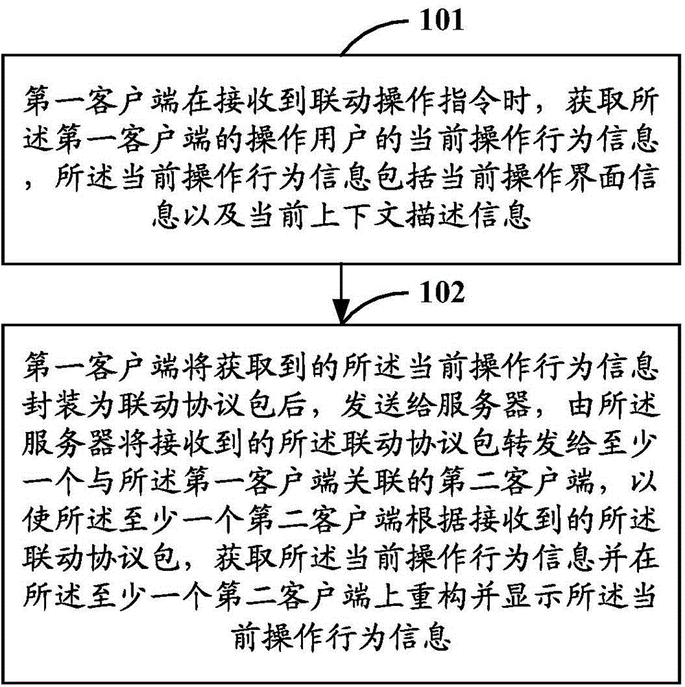
[0043] Such as figure 1 As shown, it is a schematic flow chart of the multi-terminal linkage method described in Embodiment 1 of the present application, and the multi-terminal linkage method may include the following steps:
[0044] Step 101: When the first client receives the linked operation instruction, obtain the current operation behavior information of the operating user of the first client, the current operation behavior information includes the current operation interface information and the current context description information.
[0045] Specifically, in the embodiment described in this application, the first client may generally be an instant messaging client. Of course, it should be noted that the first client can also be other clients, such as an email client or a web browser, or even a terminal device relative to the server device, such as a PC terminal or a mobile terminal, etc. , which is not limited in this embodiment of the present application.
[0046] F...
Embodiment 2
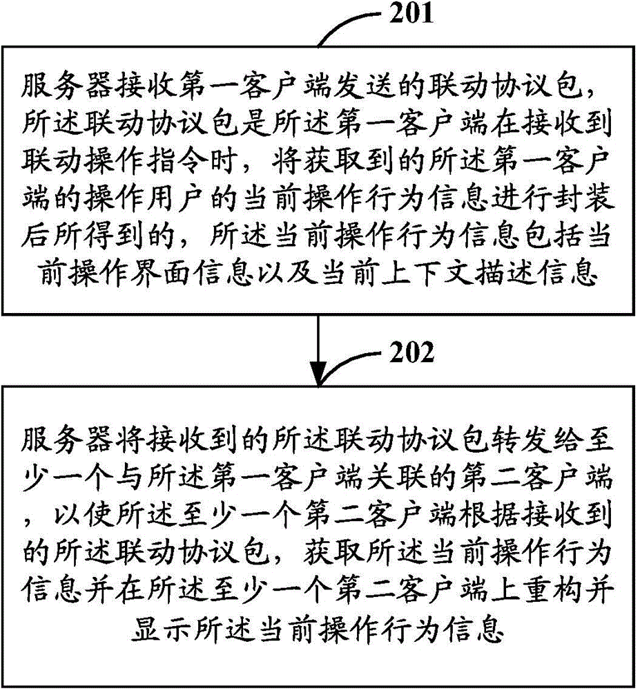
[0067] Embodiment 2 of the present application takes the action execution party as an example to further describe the multi-terminal linkage method described in Embodiment 1 of the present application. Specifically, such as figure 2 As shown, the multi-terminal linkage method may include the following steps:
[0068] Step 201: The server receives the linkage protocol packet sent by the first client, and the linkage protocol packet is the current operation of the operating user of the first client that the first client will obtain when receiving the linkage operation instruction The behavior information is obtained by encapsulating the current operation behavior information, including current operation interface information and current context description information.
[0069] Specifically, the server may receive the linkage protocol packet sent by the first client through an instant messaging channel, wherein the linkage protocol packet is the current operation behavior info...
Embodiment 3
[0078] Embodiment 3 of the present application takes the second client (that is, the client that has not received the linkage operation instruction) as an example to further illustrate the multi-terminal linkage method in Embodiment 1 of the present application. Specifically, such as Figure 4 As shown, the multi-terminal linkage method may include the following steps:
[0079] Step 301: The second client receives the linkage protocol packet from the first client forwarded by the server, and the linkage protocol packet is the information of the first client that the first client will obtain when receiving the linkage operation instruction. It is obtained after encapsulating the current operation behavior information of the operating user, the current operation behavior information includes the current operation interface information and the current context description information; wherein, the first client is the client associated with the second client end.
[0080] Specifi...
PUM
 Abstract
Description
Claims
Application Information
 - R&D
- Intellectual Property
- Life Sciences
- Materials
- Tech Scout
- Unparalleled Data Quality
- Higher Quality Content
- 60% Fewer Hallucinations
Browse by: Latest US Patents, China's latest patents, Technical Efficacy Thesaurus, Application Domain, Technology Topic, Popular Technical Reports.
© 2025 PatSnap. All rights reserved.Legal|Privacy policy|Modern Slavery Act Transparency Statement|Sitemap|About US| Contact US: help@patsnap.com