
A protection circuit for led lamps

A technology for LED lamps and protection circuits, which is applied in the direction of electric lamp circuit layout, electric light source, light source, etc., can solve the problems of LED lamp circuit damage, achieve the effects of ensuring luminous flux and service life, reducing heat generation, and preventing damage

Active Publication Date: 2018-09-14
GUANGZHOU FORDA SIGNAL
View PDF5 Cites 0 Cited by
  • Summary
  • Abstract
  • Description
  • Claims
  • Application Information

AI Technical Summary

Problems solved by technology

Existing LED car lights generally do not have a high-voltage disconnect circuit, so that there is a hidden danger that the circuit of the LED car light will be damaged by high-voltage pulses

Method used


Image

  • A protection circuit for led lamps

Examples


Embodiment Construction

[0020] The present invention will be further described below in conjunction with the accompanying drawings of the specification.

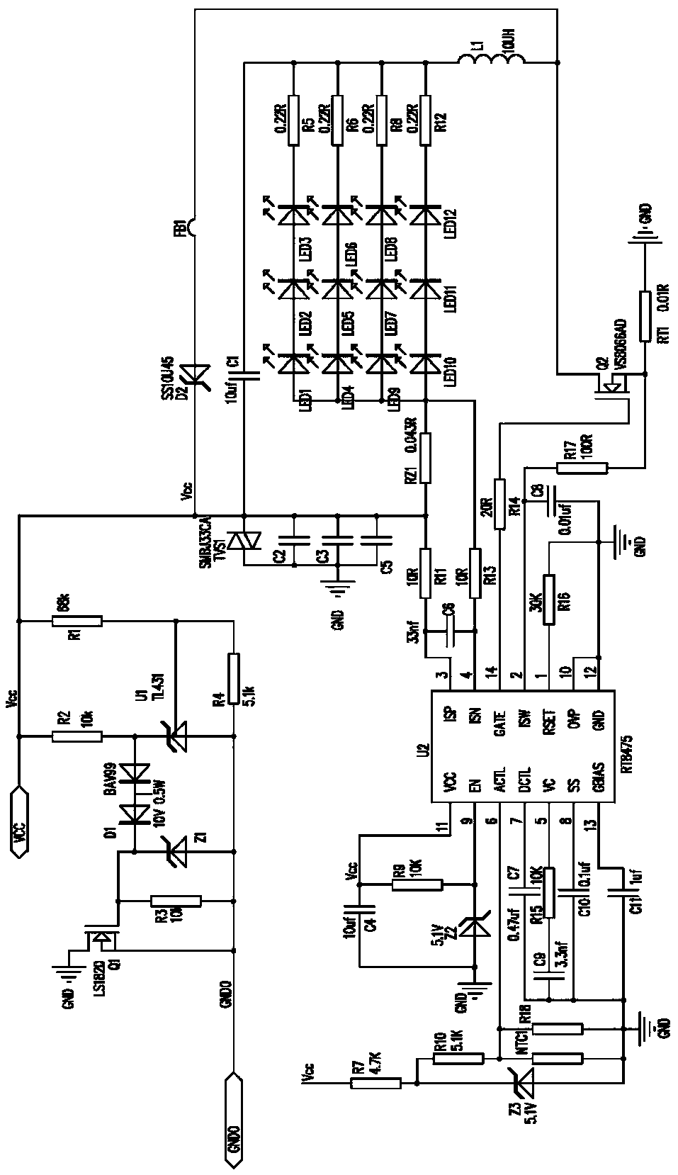
[0021] Such as figure 1 As shown, an LED lamp protection circuit includes a temperature control protection circuit, a high-voltage disconnect circuit and an LED connection circuit connected by LED chips in series and parallel. The LED connection circuit is formed by connecting a plurality of parallel LED series branches.

[0022] The temperature protection circuit is arranged on the LED light board and includes an LED drive chip U2, thermistor NTC1 and a MOS tube Q2. The model of the LED driver chip U2 is RT8475. The thermistor NTC1 is attached to the surface of the LED light board to sense the temperature of the LED light board; one end of the thermistor NTC1 is connected to the dimming terminal ACTL of the LED driver chip U2, and the other end is grounded. The control pin GATE of the LED driver chip U2 is connected to the gate of the MOS tube Q2, t...


PUM


Abstract

The invention provides a protection circuit for an LED light fixture. The protection circuit for an LED light fixture includes a temperature control protection circuit, a high voltage open circuit and an LED connection circuit, wherein the LED connection circuit is formed through series-parallel connection of LED chips; the temperature control protection circuit is arranged on an LED lamp panel, and comprises an LED driver chip U2, a thermistor NTC1 and an MOS transistor Q2; the high voltage open circuit includes a controllable precision stabilized power supply U1 and an MOS transistor Q1; the temperature of the LED lamp panel can be measured by the thermistor; the magnitude of the LED output current can be controlled through temperature variation; and the output power is suitably adjusted to reduce heat generation of LED so that the luminous flux and the service life of the LED can be guaranteed maximumly. When the input voltage of an external power supply VCC is greater than 36V and the potential of the reference electrode of the controllable precision stabilized power supply U1 is greater than 2.5V, the controllable precision stabilized power supply U1 is conducted and the MOS transistor Q1 is disconnected and the input high voltage is added to the MOS transistor Q1 so that high voltage protection is formed on other components in the circuit.

Description

Technical field [0001] The invention relates to an LED lamp, and particularly has the functions of temperature protection and high voltage disconnection for the LED lamp. Background technique [0002] The heat dissipation problem has always been one of the problems that LEDs need to solve. The heating elements of LED lamps are mainly LED chips. Several LED chips are concentrated on the LED lamp panel. When the LED lamp works, the LED lamp panel will generate a lot of heat. The current heat dissipation method of LED lamps is mainly to use a radiator and a fan to dissipate the heat of the LED lamp board. However, for some LED lamps whose heat dissipation space is limited and cannot be installed with a radiator, because there is no heat dissipation device, the temperature of this kind of lamps is likely to be too high during operation, and the luminous flux and life of the LED will be affected to a certain extent. [0003] LED lamps, especially LED car lights, are especially frequent...

Claims


Application Information

Patent Timeline
Patent Type & Authority Patents(China)
IPC IPC(8): H05B37/02
Inventor 刘信国
Owner GUANGZHOU FORDA SIGNAL
Learn More