Positioning and clamping device

A technology of positioning, clamping, and included angle, which is applied to gear tooth manufacturing devices, gear teeth, gear cutting machines, etc., can solve the problems of inability to eliminate the positioning error of the matching gap, low repeated positioning accuracy of the clamping device, and high cost of the grinding process. Achieve the effect of ensuring uniform radial expansion, ensuring processing quality, and high positioning accuracy

Inactive Publication Date: 2016-02-24
JIANGLU MACHINERY & ELECTRONICS GROUP
View PDF6 Cites 5 Cited by
  • Summary
  • Abstract
  • Description
  • Claims
  • Application Information

AI Technical Summary

Problems solved by technology

[0002] In the ordinary grinding of high-precision hardened gears, the structure of the grinding and clamping device often used is as follows: figure 2 As shown, it mainly includes three parts: the clamp body, the compression nut and the pressure plate; its main disadvantages are as follows: 1) Because the rigid shaft-hole fit is mainly used, the fit clearance is reduced by improving the machining accuracy of the clamp body and the positioning surface of the workpiece. This positioning method not only increases the processing cost, but also cannot eliminate the positioning error of the fit gap, resulting in low repeat positioning accuracy of this type of clamping device; Clamping device, making the gear grinding process cost-prohibitive

Method used


Image

  • Positioning and clamping device
  • Positioning and clamping device
  • Positioning and clamping device

Examples


Embodiment Construction

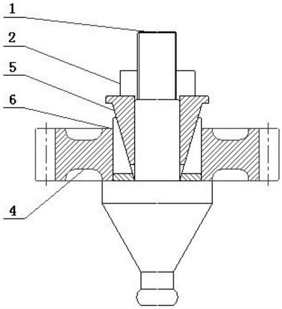
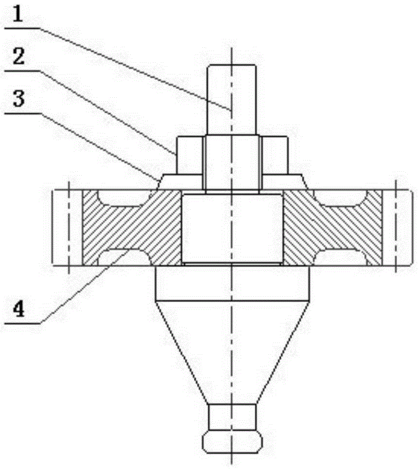
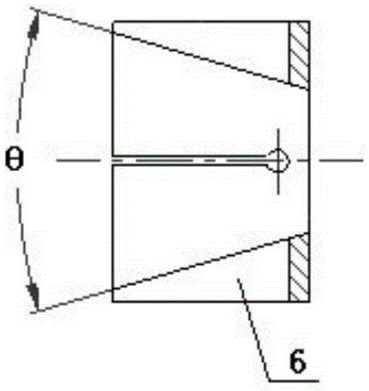
[0035] Referring to the accompanying drawings, the present invention is realized in the following way: a positioning and clamping device, which includes a clamp body 1, a compression nut 2, a compression sleeve 5 and an expansion sleeve 6; The stepped shaft of the screw thread 11, the compression sleeve 5 is a hollow cone; the expansion sleeve 6 is a cylindrical body whose inner hole is axially tapered, and the wall of the expansion sleeve 6 is provided with two or two Expansion grooves A61 evenly distributed above the strip; the expansion sleeve 6 passes through the external thread 11 end of the clamp body 1 and clings to the step surface 12, and the workpiece 4 passes through the outer circle of the expansion sleeve 6 and clings to the step surface of the clamp body 1 12. The compression sleeve 5 passes through the end of the external thread 11 of the clamp body 1 and is installed in the taper hole of the expansion sleeve 6. The compression nut 2 is connected to the end of th...


PUM


Abstract

A positioning and clamping device comprises a clamp body, a compression nut, a compression sleeve and an expansion sleeve. The clamp body is a stepped shaft, and an external thread is arranged on the cylindrical surface of one end of the clamp body. The compression sleeve is a hollow cone. The expansion sleeve is a cylinder, and an inner hole of the expansion sleeve is conical in the axial direction. Two or more expansion grooves A are uniformly distributed in the cylinder wall of the expansion sleeve. Workpieces are arranged on the outer circle of the expansion sleeve and jointly penetrate through the external thread end of the clamp body to be attached tightly to the step surface. The compression sleeve is installed in the conical hole of the expansion sleeve. The compression nut is connected with the external thread end of the clamp body, and the conical surface of the compression sleeve can squeeze the expansion sleeve to expand outwards by screwing the compression nut, so that clamping and positioning of the workpieces are achieved. A double-conical-surface expansion squeezing structure is adopted, so that no-fit-clearance positioning and clamping of the workpieces are achieved; in addition, the overall structure is scientific and reasonable, installation and using are convenient, the repeated positioning precision is high, and the manufacturing cost is low; the positioning and clamping device can be widely used for grinding or turning various workpieces with inner holes in a matched mode.

Description

technical field [0001] The invention relates to a positioning and clamping device. Background technique [0002] In the ordinary grinding of high-precision hardened gears, the structure of the grinding and clamping device often used is as follows: figure 2 As shown, it mainly includes three parts: the clamp body, the compression nut and the pressure plate; its main disadvantages are as follows: 1) Because the rigid shaft-hole fit is mainly used, the fit clearance is reduced by improving the machining accuracy of the clamp body and the positioning surface of the workpiece. This positioning method not only increases the processing cost, but also cannot eliminate the positioning error of the fit gap, resulting in low repeat positioning accuracy of this type of clamping device; The clamping device makes the cost of the gear grinding process too high. [0003] In the comprehensive transmission device, the ratio of using high-precision hard-toothed gears as parts is relatively h...

Claims


Application Information

Patent Timeline
Patent Type & Authority Applications(China)
IPC IPC(8): B23F23/06
Inventor 成钢郭湘辉刘容李楠贵
Owner JIANGLU MACHINERY & ELECTRONICS GROUP
Why Eureka
Try Eureka