

Fixed-rotor rotation apparatus
A technology of rotating devices and rotors, which can be used in rotorcraft, transportation and packaging, aircraft, etc., and can solve problems such as frequent accidents
Inactive Publication Date: 2016-02-24
申俊勇
View PDF0 Cites 0 Cited by
- Summary
- Abstract
- Description
- Claims
- Application Information
AI Technical Summary
Problems solved by technology
However, accidents occurred frequently during the flight attitude change of the aircraft.
Method used
View moreImage
Smart ImageViewing Examples

Examples
Embodiment Construction
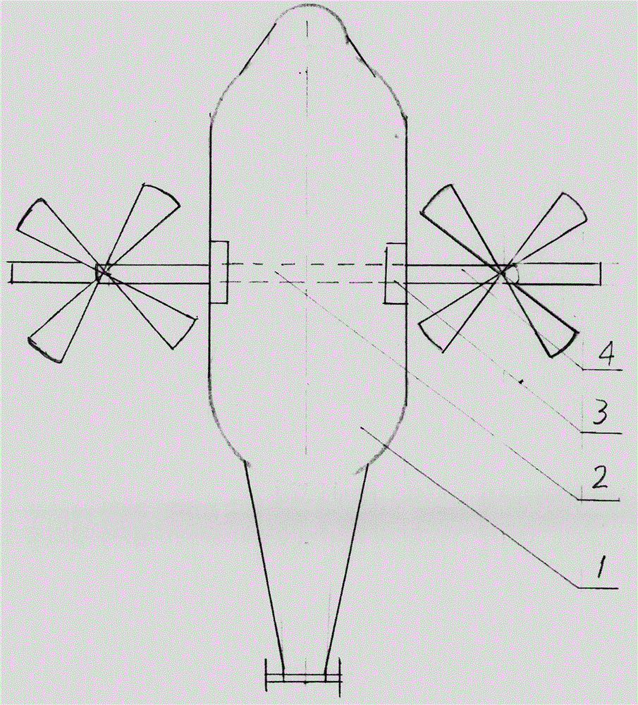
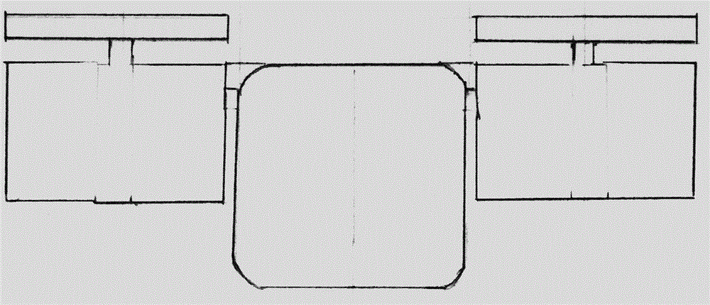
[0014] figure 1 , 2 , 3, 4, 5, 6, 7, and 8 illustrate that the present invention includes a body 1, a lever shaft 2, a pivot 3, and a fixed rotor 4. The body 1 is a rectangular warehouse structure, which is a carrier for supporting and fixing various components, structures and systems. The lever shaft 2 is horizontally arranged at the center of gravity in the middle of the upper end of the body 1, and is connected to the fixed rotor 4 left and right; The pivot 3 is arranged at the joint between the lever shaft 2 and the two sides of the machine body 1 and can control the lever shaft 2 . The fixed rotors 4 are arranged on both sides of the body 1 and are connected and fixed with the lever shaft 2 .
Login to View More PUM
 Abstract
The invention provides a fixed-rotor rotation apparatus, comprising a body, a bar shaft, rotation pivots and fixed rotors, wherein the body is of a rectangular cabin structure and is a carrier for supporting and fixing every part, structure and system, the bar shaft is transversely arranged at a centre-of-gravity position located at the middle part of the upper end of the body, and left and right ends of the bar shaft are fixedly connected with the fixed rotors, the rotation pivots are arranged at joints of two sides of the upper end of the body and the bar shaft and can control rotation of the control bar shaft to realize control of the flight attitude of an airplane, and the fixed rotors are arranged at two sides of the body and connected with the bar shaft. The fixed-rotor rotation apparatus provided by the invention realizes safe and reliable control of rotors and is larger in take-off weight and faster in flight speed compared with an American osprey transporter.
Description
technical field [0001] The invention relates to the construction and structure of a fixed-rotor rotary control system of an aircraft in the field of transport aircraft. technical background [0002] At present, the Osprey rotor transport aircraft in the United States has broken the traditional design concept and realized the combination of fixed-wing aircraft and screw-wing aircraft, which makes it have a larger load capacity and faster flight speed than traditional helicopters. However, accidents occurred frequently during the flight attitude change of the aircraft. The aircraft's fixed-wing section is below its rotors, affecting takeoff weight. Contents of the invention [0003] Aiming at the many shortcomings and deficiencies of the U.S. Osprey rotor transport aircraft, the present invention develops a key structure and structure of this type of transport aircraft - a fixed rotor rotating device. It comprises a body, a lever shaft, a pivot, and a fixed rotor. Its fea...
Claims
Login to View More Application Information
Patent Timeline
 IPC IPC(8): B64C27/24
Inventor 申俊勇
Owner 申俊勇