
A high-altitude cable climbing mechanism and robot based on elastic frame

An elastic frame and robot technology, applied in the field of robots, can solve the problems of surface protection layer damage, wire breakage and warping, danger, etc., and achieves the effect of strong pipe diameter adaptability, complete and comprehensive detection, and improved load capacity.

Active Publication Date: 2017-04-19
NANJING UNIV OF POSTS & TELECOMM
View PDF7 Cites 0 Cited by
  • Summary
  • Abstract
  • Description
  • Claims
  • Application Information

AI Technical Summary

Problems solved by technology

[0002] The robot in the prior art is uncontrollable in the degree of freedom of rotation, so it cannot complete the inspection of the entire outer cylindrical surface
[0003] In addition, most of the existing robots have complex structures, heavy weight, weak climbing ability, and weak ability to overcome obstacles. It is troublesome to adjust when adapting to different pipe diameters. For example, when the pipe diameter is different, the posture of the mechanism is different, and the elongation length of the spring is different. , in order to ensure a constant pressing force of the roller, the spring needs to be replaced frequently, and the adjustment is quite troublesome
[0004] In addition, due to the long-term use of the cable and the harsh environment, the surface protection layer is often damaged, causing the internal steel wire to break and warp
Climbing robots can easily get caught when passing through these obstacles, and are forced to stay on the high-altitude cables and cannot successfully return to the ground
And the climbing robot stays on the high-altitude cable, which is very dangerous in itself

Method used


Image

  • A high-altitude cable climbing mechanism and robot based on elastic frame
  • A high-altitude cable climbing mechanism and robot based on elastic frame
  • A high-altitude cable climbing mechanism and robot based on elastic frame

Examples


Embodiment 1

[0075] Such as Figure 5 , Image 6 , Figure 7 and Figure 8 As shown, the descending speed limiting device includes a suspension 41 , a speed increaser 42 , a brake housing 46 , a brake rotor 43 , a centrifugal spring 45 and a centrifugal block 44 .

[0076] The brake rotor, the centrifugal spring and the centrifugal block are all arranged in the brake casing, the centrifugal block and the brake rotor are hinged, and the centrifugal spring is arranged between the centrifugal block and the brake rotor.

[0077] The suspension is arranged on the left side of the speed increaser, and is sleeved on the axle end of the wheel shaft, which is fixedly connected with the left input end of the speed increaser, and the output shaft end of the speed increaser is fixedly connected with the brake rotor. Wherein, the speed increaser may be set according to actual needs, and may not be present.

[0078] When the speed is low, the inertial force is small, and under the action of the spri...

Embodiment 2

[0080] Such as Figure 9 and Figure 10 As shown, the descending speed limiting device includes a stator 52 , an impeller 53 , a compression spring 54 , a fixed disc 51 , a ball valve 56 , a speed increaser 42 and an adjusting bolt 512 . The speed increaser can be set according to actual needs, and it is not necessary.

[0081] The speed increaser 42 , the stator 52 , the fixed plate 51 and the adjusting bolt 512 are sequentially coaxially sleeved on the outer periphery of the axle end 21 of the wheel shaft.

[0082] A side of the fixed disk 51 adjacent to the stator 52 is provided with several conical valve cores 511 along the circumferential direction, preferably two.

[0083] Such as Figure 10 As shown, the stator 52 is sequentially provided with a hydraulic chamber 521 , an inner blind hole 522 and an outer blind hole 523 which communicate with each other from the inside to the outside; the hydraulic chamber 521 is provided with an impeller 53 set on the axle end 21 of...

Embodiment 3

[0086] Such as Figure 11 As shown, the descending speed limiting device also includes a rotor 57 and an inertia block 58 in addition to all the components in Embodiment 2. The rotor 57 is sleeved on the axle shaft end 21 on the right side of the fixed disk 51 . The left side of the rotor is provided with several inclined chute 571 along the circumferential direction, and each inclined chute 571 is provided with an inertia block 58 , and each inertia block 58 has an inclined surface 581 matched with the inclined chute 571 .

[0087] When the fluid flows through the above-mentioned damping holes, resistance is generated, and the magnitude of the resistance is related to the opening degree of the damping holes. When rising, the fluid passes through the inner blind hole and flows from the right side of the steel ball to the left side, and the damping hole has no effect. When descending, the inner blind hole is cut off by the steel ball (effect of spring force), the fluid passes...


PUM


Abstract

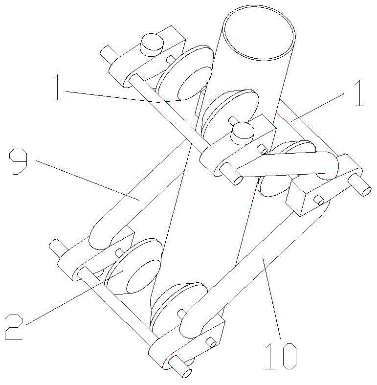
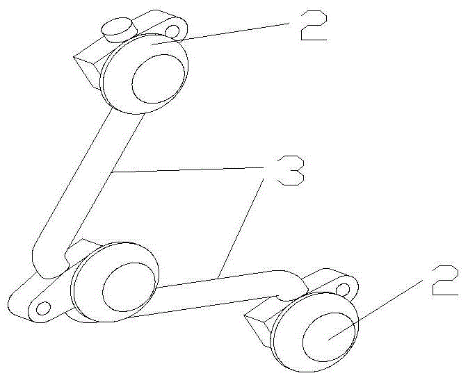
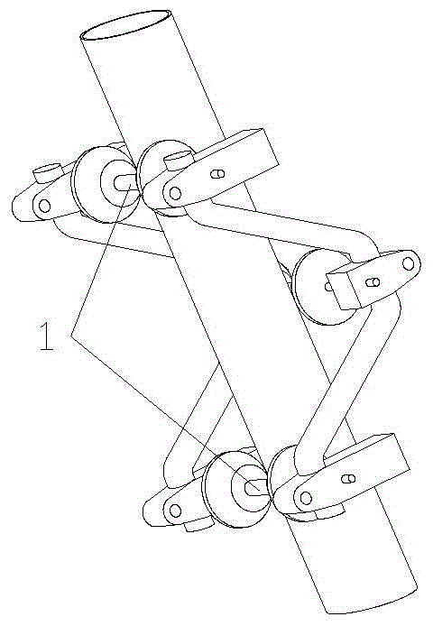
The invention discloses a high-altitude cable rope climbing mechanism and robot based on an elastic frame. The high-altitude cable rope climbing mechanism comprises three drive wheel sets, a connecting device, a descent speed limiting device and obstacle induction devices. The connecting device comprises three parallel connecting rods. Each idler wheel can serve as a drive wheel and is conic. The side, making contact with a cable rope, of each idler wheel is provided with stripes. The deviation directions of the stripes on the two idler wheels in each drive wheel set are opposite. By the adoption of the structure, when the idler wheels rotate in the same direction, the robot climbs upwards; and when the idler wheels rotate in the opposite directions, the robot does not perform climbing operation and rotates around the center of the cable rope at the angular speed, and therefore the whole outer cylindrical face is detected. In addition, the braking force is increased along with the increase of the descending speed, the descending speed and the braking force are in a dynamic balanced process, and the robot can descend at a constant speed or nearly a constant speed. Meanwhile, the outer cylindrical face of the cable rope can be subjected to circumferential fault detection at 360 degrees, and no detection dead angle exists.

Description

technical field [0001] The invention relates to a robot for fault detection of stay cables of long-span cable-stayed bridges or other high-altitude poles and transmission lines, in particular to a high-altitude cable climbing mechanism based on an elastic frame. Background technique [0002] The robots in the prior art are all uncontrollable in the degree of freedom of rotation, so the detection of the entire outer cylindrical surface cannot be completed. [0003] In addition, most of the existing robots have complex structures, heavy weight, weak climbing ability, and weak ability to overcome obstacles. It is troublesome to adjust when adapting to different pipe diameters. For example, when the pipe diameter is different, the posture of the mechanism is different, and the elongation length of the spring is different. , in order to ensure the constant pressing force of the roller, the spring needs to be replaced frequently, and the adjustment is quite troublesome. [0004] ...

Claims


Application Information

Patent Timeline
Patent Type & Authority Patents(China)
IPC IPC(8): E01D19/10
Inventor 徐丰羽申景金蒋国平
Owner NANJING UNIV OF POSTS & TELECOMM
Learn More