High-performance airfoil for fan

A high-performance, airfoil-shaped technology, applied in the components of pumping devices for elastic fluids, non-variable-capacity pumps, machines/engines, etc., can solve problems such as poor matching, and achieve excellent matching and energy efficiency. High value, low noise effect

Active Publication Date: 2016-02-24
XIN CHANG COUNTRY SAN XIN AIR CONDITIONING FAN CO LTD
View PDF7 Cites 6 Cited by
  • Summary
  • Abstract
  • Description
  • Claims
  • Application Information

AI Technical Summary

Problems solved by technology

[0004] The present invention aims at the situation that the airfoil used by the existing low-speed fan blades does not match well with the actual working conditions, and provides a high-performance fan airf

Method used


Image

  • High-performance airfoil for fan
  • High-performance airfoil for fan
  • High-performance airfoil for fan

Examples


Example Embodiment

[0065] The accompanying drawings disclose an embodiment of the present invention in a non-limiting manner. The technical solution of the present invention will be described in detail below in conjunction with the accompanying drawings.

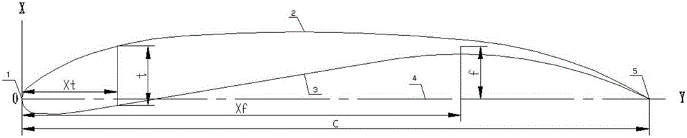
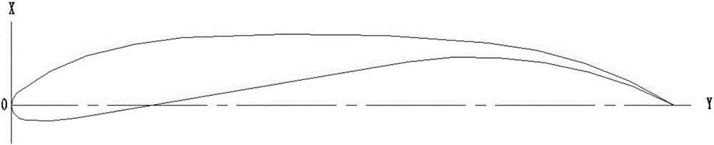
[0066] The design principle of the airfoil for a high-performance fan of the present invention is: firstly, in combination with the operating conditions of the low-speed fan, the aerodynamic analysis technology of the aviation industry is adopted to design a high-performance airfoil that matches the actual operating conditions of the fan. Special airfoil for fan. Since the main performance of the airfoil largely depends on the shape of its upper and lower surfaces or mid-curves, especially for low-speed airfoils, the rules of the upper and lower surfaces of the designed high-performance fan-specific airfoils are further studied. The characteristics, the distribution law of the upper and lower surfaces of the high-performance airfoil for fans, the...


PUM


Abstract

The invention relates to a high-performance airfoil for a fan, in particular to a high-performance airfoil for a fan, which is designed by applying an advanced pneumatic analysis technology in an aviation technology according to actual working conditions of low Reynolds number (generally lower than 106) of a small-size and low-rotating-speed fan; the invention discloses a maximum camber and a position thereof of the airfoil, a maximum thickness and a position thereof, an equation satisfied by upper and lower surfaces and an airfoil coordinate; f is the maximum camber; Xf is a transverse coordinate value of the maximum camber of the airfoil; t is the maximum thickness; Xt is a transverse coordinate vale of the maximum thickness of the airfoil; and C is a chord length. An original point of a coordinate system of the airfoil is defined as a front edge point of a middle arc line of the airfoil; an X axle is overlapped with a chord line; the direction is to point to the airfoil back edge from the airfoil front edge; and a Y axle is perpendicular to a direction of bending the X axle to the middle arc line of the airfoil. Under the same working conditions, compared with a traditional fan airfoil, the fan adopting the airfoil is better in matchability with actual working conditions, higher in air volume, lower in noise and higher in energy efficiency value.

Description

Technical field: [0001] The invention relates to a high-performance airfoil for a fan, in particular to a low-speed fan with a low working Reynolds number (generally less than 10 6 ) airfoil designed for actual working conditions. Background technique: [0002] With the development of industrial technology, low-speed fans are more and more widely used in residential life and industrial production, such as ceiling fans, air-conditioning fans, cooling fans, etc. However, the blade airfoil of the traditional low-speed fan has become less and less suitable for people's pursuit of high efficiency, energy saving and low noise. [0003] The fan blade is the main component that determines the performance of the fan, and the cross-sectional shape (airfoil) of the blade is the key to determining the performance of the fan blade. There are many kinds of airfoils in the existing literature, and the most advanced airfoil is the aircraft wing airfoil used in the aviation industry. Other...

Claims


Application Information

Patent Timeline
IPC IPC(8): F04D29/26F04D29/66
CPCF04D29/26F04D29/666F05D2240/30
Inventor 潘旭光吕刚张胜利
Owner XIN CHANG COUNTRY SAN XIN AIR CONDITIONING FAN CO LTD
Why Eureka
Try Eureka