Planetary transmission structure

A technology of planetary transmission and planetary carrier, which is applied in the direction of transmission, transmission parts, gear transmission, etc. It can solve the problems of high requirements for heat treatment and processing, increased axial clearance of the sun gear, and poor results.

Inactive Publication Date: 2016-02-24
HUNAN OIL PUMP
View PDF6 Cites 0 Cited by
  • Summary
  • Abstract
  • Description
  • Claims
  • Application Information

AI Technical Summary

Problems solved by technology

[0002] In the NGW planetary transmission, due to the axial fixation between the sun gears, friction will inevitably occur due to relative motion, which will cause the axial gap between the sun gears to increase, and the reducer will heat up, thus affecting the planetary reducer. life
In order to r

Method used


Image

  • Planetary transmission structure

Examples


Embodiment Construction

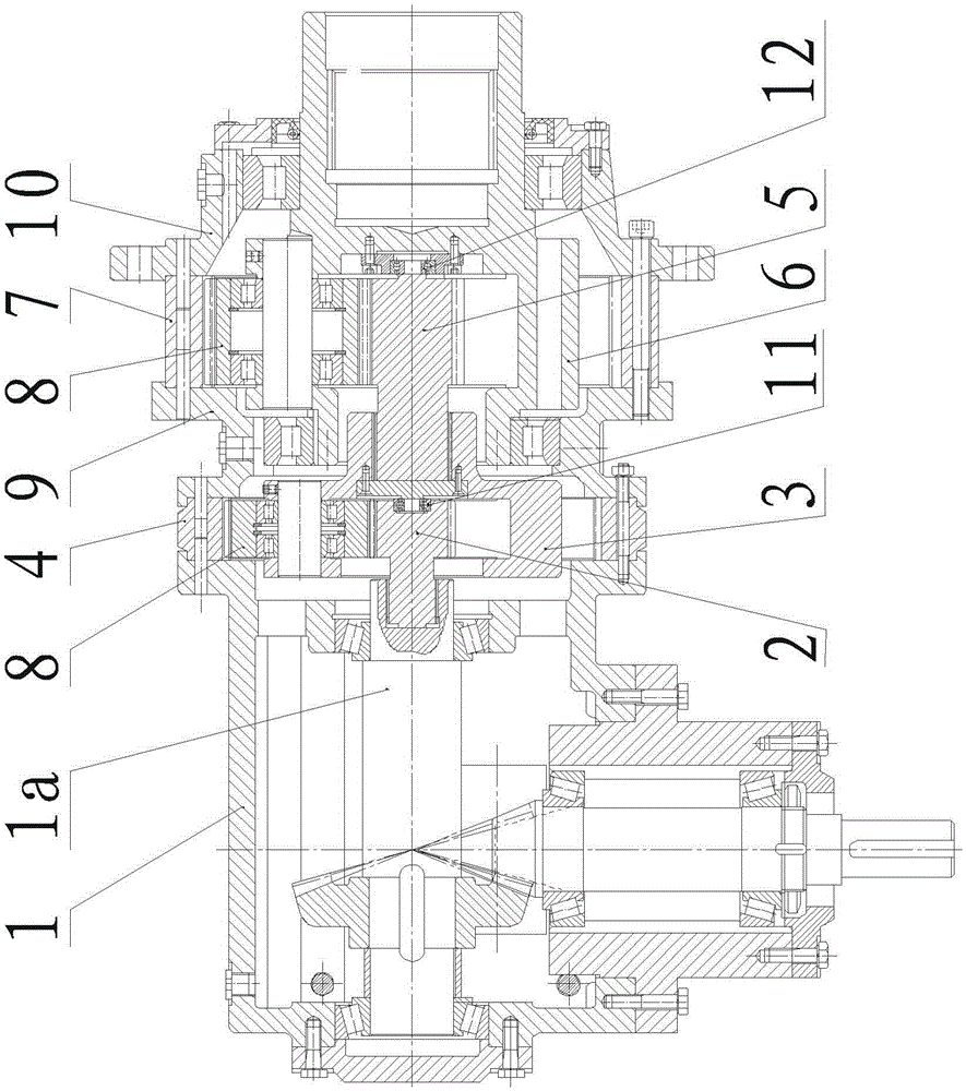
[0015] like figure 1 The shown planetary transmission structure includes a single-stage bevel gear box 1, a first sun gear 2, a first planet carrier 3, a first internal gear 4, a second sun gear 5, a second planet carrier 6, a second internal gear Gear 7, the first planet carrier 3 and the second planet carrier 6 are equipped with planetary gears 8, the first internal gear 4 and the second internal gear 7 are connected by a connecting support 9, the second The other end of the internal gear 7 is equipped with a connecting flange 10. The single-stage bevel gearbox 1 includes an output shaft 1a, and the output shaft 1a, the first sun gear 2, and the second sun gear 5 are located on the same axis. The front end of the first sun gear 2 is mounted on the output shaft 1a, a first bearing 11 is installed between the rear end of the first sun gear 2 and the front end of the second sun gear 5, and the outer ring of the first bearing 11 Fixed on the rear end face of the first sun gear ...


PUM


Abstract

The invention provides a planetary transmission structure. The planetary transmission structure comprises a single-stage bevel gear box, a first sun gear, a first planetary carrier, a first inner gear, a second sun gear, a second planetary carrier and a second inner gear, wherein the single-stage bevel gear box comprises an output shaft; the output shaft, the first sun gear and the second sun gear are positioned on the same axis; the front end of the first sun gear is mounted on the output shaft; a first bearing is mounted between the rear end of the first sun gear and the front end of the second sun gear; an outer ring of the first bearing is fixed to the rear end surface of the first sun gear, and an inner ring of the first bearing is fixed to the front end surface of the second sun gear; the first planetary carrier is fixedly connected to the front end of the second sun gear; a second bearing is mounted between the rear end of the second sun gear and the second planetary carrier. According to the technical scheme, the planetary transmission structure has the advantages that two sun gears are correspondingly independently rotated around the corresponding bearings, so that direct contact can be avoided, and the friction can be greatly reduced.

Description


Claims


Application Information

Patent Timeline
Owner HUNAN OIL PUMP
Why Eureka
Try Eureka