Optical method, device and application for measuring supersonic wave sound pressure and sound intensity

An optical method and ultrasonic technology, applied in the direction of measuring ultrasonic/sonic/infrasonic waves, measuring devices, using wave/particle radiation, etc., can solve problems such as complex manufacturing process and limited dynamic range of sound pressure

Inactive Publication Date: 2016-02-24
SOUTH CHINA NORMAL UNIVERSITY
View PDF9 Cites 15 Cited by
  • Summary
  • Abstract
  • Description
  • Claims
  • Application Information

AI Technical Summary

Problems solved by technology

The Fabry-Perot interferometer has the characteristics of small size and good stability, but it has t...

Method used


Image

  • Optical method, device and application for measuring supersonic wave sound pressure and sound intensity
  • Optical method, device and application for measuring supersonic wave sound pressure and sound intensity
  • Optical method, device and application for measuring supersonic wave sound pressure and sound intensity

Examples


Embodiment 1

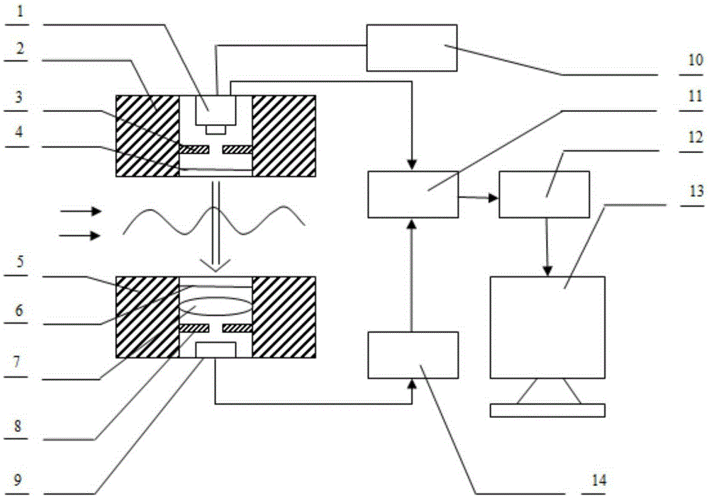
[0057] An ultrasonic sound pressure and sound intensity detection device, such as figure 2 As shown, it includes light source 1, light source seat 2, exit diaphragm 3, exit window 4, detector seat 5, entrance window 6, convex lens 7, filter diaphragm 8, photodetector 9, power supply 10, signal compensation circuit 11, Signal acquisition circuit 12, computer 13, signal inversion and amplification circuit 14. Wherein, along the light beam advancing direction, the light source 1, the exit diaphragm 3, the exit window 4, the entrance window 6, the convex lens 7, the filter diaphragm 8 and the photodetector 9 are arranged in sequence to form the optical path components; the exit diaphragm 3, the convex lens 7 Coaxial with filter diaphragm 8; light source 1 is connected to power supply 10 and signal compensation circuit 11 respectively; photodetector 9, signal inversion and amplification circuit 14, signal compensation circuit 11, signal acquisition circuit 12 and computer 13 are c...


PUM


Abstract

The invention discloses an optical method, a device and an application for measuring supersonic wave sound pressure and sound intensity The optical method comprises steps illuminating the supersonic wave by a parallel beam in a direction perpendicular to the propagation of the supersonic wave, obtaining a diffraction frequency spectrum of a raster, receiving zero order spectrum diffracted light, obtaining a corresponding voltage value through a reversing and amplification circuit and a sampling processing circuit, obtaining the amplitude of the sound pressure to be measured by comparing with a calibration value obtained beforehand and calculating the sound intensity. The device provided by the invention comprises a power supply, a signal compensation circuit, a signal collection circuit, the signal reversing circuit, the signal amplification circuit, a computer, a light source, a light outgoing diaphragm, a light outgoing window, a light incident window, a convex lens, a filtering diaphragm and a photoelectric detector, wherein the light source, the light outgoing diaphragm, the light outgoing window, the light incident window, the convex lens, the filtering diaphragm and the photoelectric detector are successively arranged along the heading direction; the light source is connected to the power supply and the signal compensation circuit; the photoelectric detector, the signal reversing and amplification circuit, the signal compensation circuit, the signal collection circuit and the computer are successively connected. The invention has strong measurement directivity and practicability.

Description

technical field [0001] The invention belongs to the technical field of optical measurement and measurement, and relates to an optical method and device for measuring ultrasonic sound pressure and sound intensity and an application thereof. Background technique [0002] Measuring the sound pressure of sound waves or ultrasonic waves propagating in liquid has practical significance, and has important applications in the fields of sonar detection and positioning and underwater acoustic communication. There are many traditional methods and devices for measuring sound waves or ultrasonic sound pressure in liquids, most of which are based on the principle of electromagnetics. There are mainly moving coil type, electrostatic type, variable reluctance type, magnetostrictive type and piezoelectric type. For example, the sound pressure sensor based on the solid piezoelectric effect can directly convert the sound pressure signal into a voltage signal, and measure the voltage by electr...

Claims


Application Information

Patent Timeline
IPC IPC(8): G01H9/00
Inventor 黄佐华吴舒哲熊亮
Owner SOUTH CHINA NORMAL UNIVERSITY
Why Eureka
Try Eureka