LED chip junction temperature testing method

A technology of LED chips and testing methods, applied in the field of semiconductors, can solve problems such as heat loss, insufficient switching speed of current source meters, and affecting test results, so as to avoid the impact of heat loss and reduce the cost of testing equipment

Inactive Publication Date: 2016-02-24
JIANGSU XINGUANGLIAN SEMICON
View PDF4 Cites 8 Cited by
  • Summary
  • Abstract
  • Description
  • Claims
  • Application Information

AI Technical Summary

Problems solved by technology

During the test, the switching speed of the current source meter is often not fast enough to cause heat loss, which affects the test results

Method used


Image

  • LED chip junction temperature testing method

Examples


Embodiment

[0017] The LED chip junction temperature testing method of the present invention comprises the following steps:

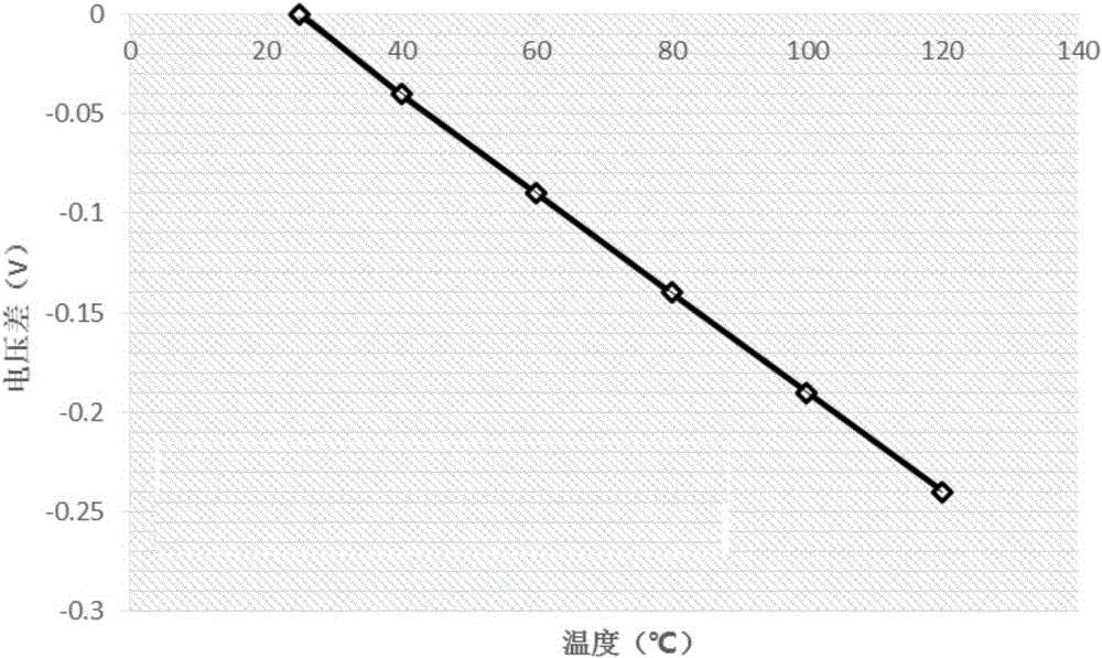
[0018] (1) Modeling: Under the driving current, the LED chip collects the voltage values ​​of the driving current at ambient temperatures such as 25°C, 40°C, 60°C, 80°C, 100°C, and 120°C; Aging current;

[0019] (2) Modeling calculation: According to the different temperatures obtained in step (1) and the corresponding voltage difference, make a table to obtain a function fitting formula y=ax+b, where x is the abscissa, representing the ambient temperature; y is the ordinate , represents the voltage difference; a is the slope, and b is the intercept; the linear function curve obtained in this embodiment is as follows figure 1 As shown, y=-0.002518x+0.061661;

[0020] (3) Actual measurement: use the driving current to drive the LED chip to the thermal equilibrium state, and obtain the voltage value under the thermal equilibrium state; the driving current is the ag...


PUM


Abstract

The invention relates to an LED chip junction temperature testing method, and the method is characterized in that the method comprises the following steps: (1) modeling: an LED chip is driven by a drive current to collect voltage values of the drive current under the temperatures of 25 DEG C, 40 DEG C, 60 DEG C, 80 DEG C, 10 DEG C and 120 DEG C; (2) modeling calculation: obtaining a linear function fitting function y=ax+b according to the temperature obtained at step (1) and the corresponding voltage values, wherein x is x-coordinate and represents the environment temperature, y is y-coordinate and represents a voltage difference, a is slope, and b is intercept; (3) actual measurement: driving the LED chip to be in a state of thermal equilibrium through employing the driving current, and obtaining a voltage value at the state of thermal equilibrium; (4) junction temperature calculation: obtaining a thermal equilibrium voltage and a normal temperature modeling voltage difference delta Vf, and obtaining the junction temperature of the LED chip according to a junction temperature calculation formula Tj=(delta Vf-b) / a. The drive current employs an aging current of a corresponding LED chip. The method can obtain accurate junction temperature of the LED chip, and is lower in testing equipment cost.

Description

technical field [0001] The invention relates to a method for testing the junction temperature of an LED chip, which belongs to the technical field of semiconductors. Background technique [0002] The working junction temperature of the LED chip has a very important impact on the life of the LED. Every time the junction temperature rises by 10 degrees, its life will be reduced by half, and the conversion efficiency will decrease after the junction temperature rises, resulting in energy waste. [0003] Using the voltage method to measure the junction temperature is a common method in the industry, but it requires a high-pulse source meter, and the equipment is very expensive, which is difficult for ordinary companies to afford. The main process of the existing voltage method to measure the junction temperature is: (1) Use the standard voltage method to model, and the current uses a small current: 0.1~0.5mA; (2) After the normal driving current reaches thermal equilibrium, quic...

Claims


Application Information

Patent Timeline
Patent Type & Authority Applications(China)
IPC IPC(8): G01R31/26
CPCG01R31/26
Inventor 黄慧诗闫晓密张秀敏周锋
Owner JIANGSU XINGUANGLIAN SEMICON
Why Eureka
Try Eureka