Electric power construction grounding device

A grounding device and power construction technology, applied in the direction of circuits, connections, electrical components, etc., can solve the problems of insufficient contact surface, serious safety hazards, easy displacement of wires, etc., and achieve the effect of preventing slipping out.

Inactive Publication Date: 2016-02-24
谭焕玲
View PDF2 Cites 3 Cited by
  • Summary
  • Abstract
  • Description
  • Claims
  • Application Information

AI Technical Summary

Problems solved by technology

These three types of grounding joints have the following disadvantages: ①During the tightening process of the flat screw type, due to the gradual force at the contact position as the screw is pressed, the wire is prone to shift, resulting in poor reliability at the clamping point; ②Double spring Both the compression type and the screw type have the problem of being unable to compress the wire when the wire is stuck, which may easily lead to insufficient contact surface, short-circuit current is not up to standard, and flickering is likely to occur; ③ Since the direction of the grounding head is fixed, it cannot be operated in any direction. It cannot meet the multi-directional operation requirements of the switchgear. In practice, it often happens that the operator's position and the wire are not in a vertical position. When holding a 2-meter-long grounding device to stably hook the wire, it is an extremely difficult job. ; ④The effective insulation distance is not enough due to the change of the operating direction;

Method used


Image

  • Electric power construction grounding device
  • Electric power construction grounding device
  • Electric power construction grounding device

Examples


Embodiment 1

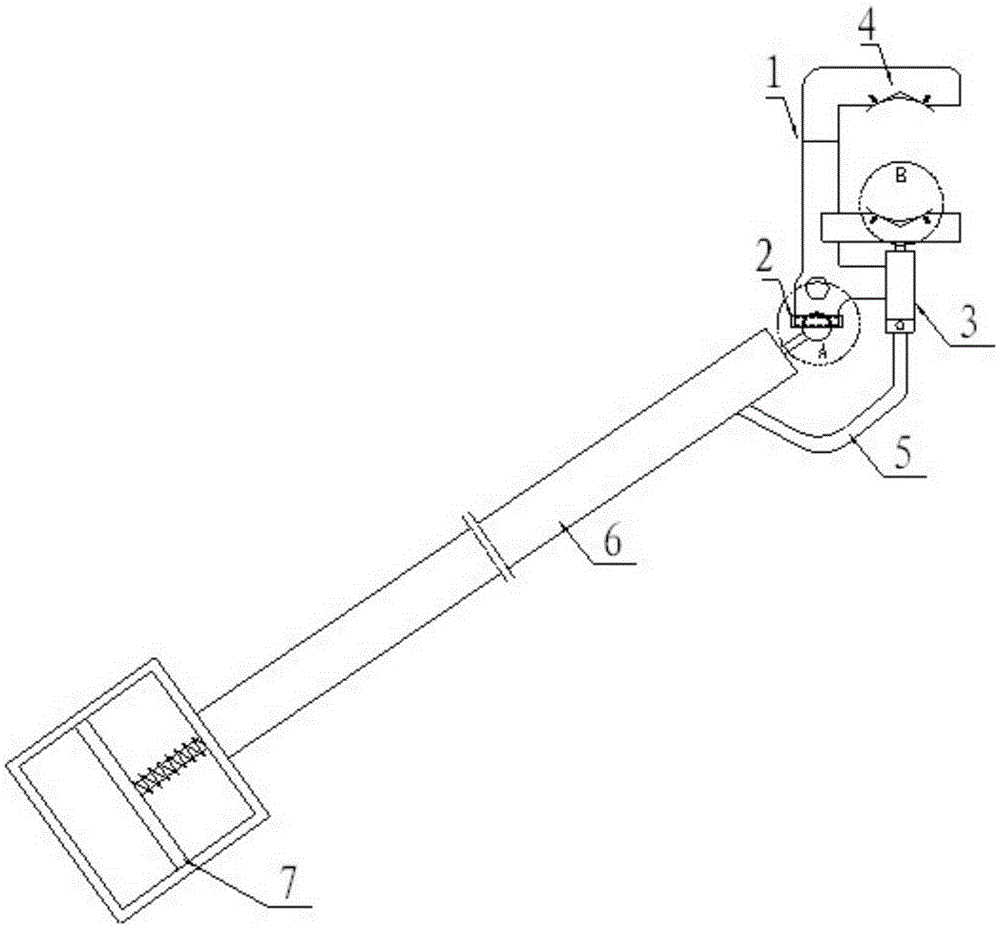
[0021] Such as figure 1 As shown, the electric power construction grounding device of the present invention mainly includes two parts, an insulating operating rod 6 and a grounding head. The universal joint 2 is used to connect the grounding head and the insulating operating rod 6 to realize any angle change of the grounding head.

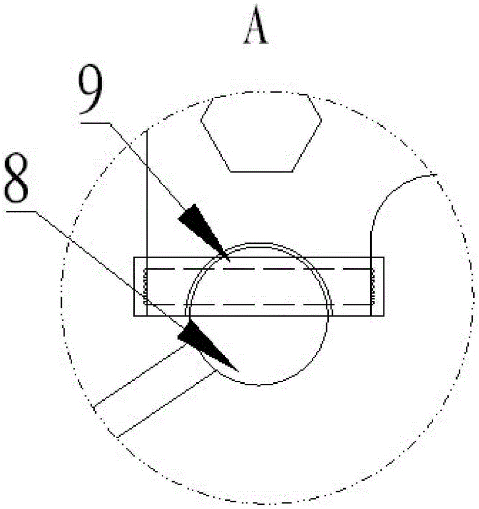
[0022] Such as figure 2 As shown, the universal joint 2 includes a spherical head 8, a hemispherical slot and a screw 9, wherein the spherical head 8 is fixed on the top of the insulating operating rod, and the bottom end of the grounding head is provided with a hemispherical slot, and the hemispherical slot and the spherical head 8 fit, so that the ground head can be rotated in any direction, and the ground head corresponding to the position of the hemispherical slot is provided with a screw 9 that penetrates the hemispherical slot and is used to fix the spherical head.

[0023] The ground head includes a handle 11 connected to the insulating op...


PUM


Abstract

The invention provides an electric power construction grounding device. A grounding end and an insulating operation rod are connected through a universal joint, any angle change of the grounding end can be realized, an operator is enabled to judge and adjust the angel of the grounding end in the usage process according to the positions of himself and an electric wire, and when the grounding end is adjusted to a suitable angle, the operation is completed just by tightening a screw, so that the operation in any direction is available; in addition, a hydraulic system is used, so that the problem of displacement or unavailable pressing caused by manual rotation or spring pressing in the prior art is solved. Furthermore, a groove is formed in a clamping surface of a bayonet, and a clamped sheet made of an elastic material is installed in the groove. In a usual force free case, the clamped sheet is in a flat state, and when the clamped sheet is hung on a line, the clamped sheet is tightly pressed with the effect of hydraulic pressing, a spring is pressed, and two ends of the clamped sheet go up and the middle part go down under the effects of the spring and the groove, so that a conductive wire is wrapped tightly, and the conductive wire is prevented from sliding out.

Description

technical field [0001] The invention relates to the field of special tools used in electric power maintenance and construction, and more specifically, relates to a grounding device for electric power construction. Background technique [0002] The grounding wire is an important tool to ensure the safety of workers in the event of unexpected voltage on equipment and lines that have been powered off. The portable short-circuit grounding device is a temporary grounding device commonly used in the process of electric power maintenance and construction. Its function is to prevent equipment and lines from suddenly receiving electricity, electric shock caused by electrostatic induction caused by nearby charged objects, or misconnection during the construction of lines and substations. The remaining charge is discharged during the gate to ensure the personal safety of the staff during the maintenance process. [0003] The existing portable short-circuit grounding device is mainly c...

Claims


Application Information

Patent Timeline
IPC IPC(8): H01R4/66H01R35/00
CPCH01R4/66H01R35/00
Inventor 谭焕玲
Owner 谭焕玲
Why Eureka
Try Eureka