[0027] In order to enable those skilled in the art to better understand the technical solutions in the present invention, the technical solutions in the embodiments of the present invention will be clearly and completely described below in conjunction with the drawings in the embodiments of the present invention. Obviously, the described The embodiments are only some of the embodiments of the present invention, not all of them. Based on the embodiments of the present invention, all other embodiments obtained by persons of ordinary skill in the art without making creative efforts shall fall within the protection scope of the present invention.
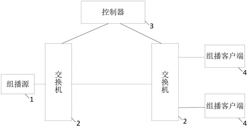
[0028] figure 1 A system frame diagram of information transmission provided by an embodiment of the present invention. like figure 1 As shown, the system includes a multicast source 1, a switch 2, a controller 3, and a multicast client 4, wherein the number of the switch 2 can be multiple, and the switch 2 can be connected to the multicast source 1 or The multicast client 4 is connected to collect and distribute multicast data. The controller 3 can be connected with the switch 2 so as to control the switch 2 . Specifically, the workflow of the system can be described as follows:
[0029] S1: The switch reports configuration information to the controller, where the configuration information includes at least MAC address and port information of the switch.
[0030] In the embodiment of the present invention, the switch can be connected with the controller, so as to receive various control instructions issued by the controller and transmit various information to the controller. The switch often has a MAC address and information about each port, and the MAC address can be used as an identifier of the switch to distinguish each switch from the network. After acquiring the MAC address and port information of the switch, the switch can be accessed through the MAC address. Through the port information, an access can be initiated to the multicast source or multicast client connected to the switch.
[0031] In the embodiment of the present invention, all main control processes may be configured in the controller. Therefore, it is necessary for the controller to understand the topology of the entire network, so as to be able to deploy information and issue control commands in the network. Each switch is a portal of the multicast source and the multicast client in the network, and the multicast source and the multicast client can be accessed through the switch. Therefore, in this embodiment of the present invention, a connection between the switch and the controller may be established in advance, so that the switch reports its own configuration information to the controller. As mentioned above, the configuration information includes at least the MAC address and port information of the switch. In this way, the controller can use the MAC address and port information to perform data intercommunication with the multicast source and the multicast client through the switch.
[0032] Specifically, in a preferred embodiment of the present invention, the switch may be an OpenFlow switch, and the OpenFlow switch may be composed of a flow table, a security channel, and an OpenFlow protocol. In this case, the switch may initiate an OpenFlow channel to communicate with the controller. The process of OpenFlow channel initialization can be regarded as the process of establishing a communication channel. In this process, the switch can configure required parameters for the communication channel to ensure normal communication with the controller. After the OpenFlow channel is initialized, the switch may use a private Experimenter message to report configuration information to the controller through the OpenFlow channel. The format of the Experimenter message can be as shown in Table 1:
[0033] Table 1 Format of Experimenter message
[0034]
[0035]In Table 1, the value of the Experimenter is 255. In the embodiment of the present invention, in order to use the Experimenter normally, it is necessary to invent the Experimenter with a value of 255 from the ONF (Open Network Foundation) organization. The value of Experimentertype is 1, indicating that the direction of the Experimenter message is from the switch to the controller. PortID represents the port ID of the switch. As shown in Table 1, the maximum number of port IDs reported by the switch is 128.
[0036] S2: According to the configuration information and the LLDP protocol, the controller determines the network topology.
[0037] After acquiring the configuration information of the switch, the controller can initiate access to the switch according to the configuration information. Further, since the switch is connected to the multicast source or the multicast client, it can communicate with the multicast source or the multicast client. In the embodiment of the present invention, in order to regulate the data between the multicast source and the multicast client in the network, the controller needs to determine the network topology. Specifically, the controller may determine the network topology according to the configuration information and the LLDP protocol (Link Layer Discovery Protocol). In the embodiment of the present invention, the controller may extract the MAC address and port information of the switch from the configuration information. Through the MAC address and port information, it is possible to initiate access to the multicast source or multicast client in the network connected to the port of the switch. Specifically, the controller may send an LLDPDU (LinkLayerDiscoveryProtocolProtocolDataUnit, link layer discovery protocol data unit) to the multicast source or multicast client connected to the switch according to the LLDP protocol. Multiple TLVs (Type/Length/Value) may be encapsulated in the LLDPDU, and the TLVs may respectively record information such as main capabilities, management addresses, device identifiers, and interface identifiers of the controller. After the information is encapsulated in the LLDPDU, the controller can send the information to the multicast source and the multicast client in the network via each switch. After the multicast source or the multicast client receives the LLDPDU, the LLDPDU may be stored according to a preset standard. The preset standard may, for example, be in the form of MIB (ManagementInformationBase, Management Information Base). After the multicast source or multicast client saves the LLDPDU, it can be used by the network management system to query and judge the communication status of the link, so as to establish a neighbor relationship with the controller, and the controller can obtain Network Topology.
[0038] S3: The controller acquires an IGMP control message from the switch.
[0039] After determining the network topology, the controller can regulate the data transmission between the multicast source and the multicast client in the network. First, the controller can obtain an IGMP control message from the switch, and the IGMP control message can include three versions, namely IGMPv1, IGMPv2 and IGMPv3. Among them, the embodiment of the present invention can adopt the IGMPv3 version with the most complete functions. The IGMP control message can include a report message (Report), a query message (Query) and a leave message (Leave), and each type of message can record the different communication states of the multicast source and the multicast client . In the IGMP control message, the IPv4 multicast address for data transmission and the input port number for data transmission can be recorded, so that the data can be accurately transmitted to the destination according to the IPv4 multicast address and input port number.
[0040] In an actual application scenario, the IGMP control message is often encapsulated into a Packet_In message by the switch, and then the switch sends the encapsulated Packet_In message to the controller. After analyzing the Packet_In message, the controller can still obtain various information in the IGMP control message.
[0041] S4: According to the network topology and the IGMP control message, the controller generates a flow table and delivers the flow table to the switch.
[0042] After the controller determines the network topology and obtains the IGMP control message, it can control the data transmission in the network topology according to the data transmission information recorded in the IGMP control message. Specifically, the controller may extract IPv4 multicast address information and input port information from the IGMP control message, and establish a mapping relationship between the IPv4 multicast address and the input port according to the network topology. For example, multiple pieces of data transmission information are recorded in the IGMP control message, for example, data is transmitted to the first input port of the first IPv4 multicast address, and data is transmitted to the second input port of the third IPv4 multicast address. input port. In this way, the controller can associate the first IPv4 multicast address with the first input port, and associate the third IPv4 multicast address with the second input port, thereby establishing an IPv4 Mapping relationship between multicast addresses and input ports. According to the mapping relationship, the controller can generate a flow table and deliver the flow table to the switch. In the embodiment of the present invention, the switch may be responsible for high-speed data forwarding, and in the process of high-speed data forwarding by the switch, the forwarding basis is the flow table. The flow label may include a header field, a counter, and an operation, wherein the header field may include a data input port, a MAC source address, a MAC destination address, an Ethernet type, a VLAN ID, an original IP address, an IP destination address, and an IP port, A series of information such as TCP source port and TCP destination port; the counter can include statistics of data packets and bytes in the data; the operation can indicate whether to forward data to a port, or to forward data to a controller, or to discard data , or send the data to normal processing. Through the flow table, the switch knows where the data comes from and where the data should be forwarded. After the controller establishes the mapping relationship between the IPv4 multicast address and the input port in the IGMP control message, it can generate a flow table for data transmission according to the mapping relationship, and send the flow table to the switch to control the switch to forward data.
[0043] In the embodiment of the present invention, according to different types of IGMP control packets, the processing flow of the controller is also different. When the IGMP control message is a Report message, the controller can obtain the IPv4 multicast address and input port information therein. According to the acquired IPv4 multicast address, the controller can query the multicast source, and generate a multicast forwarding table according to the determined network topology. The multicast forwarding table may record multicast sources and multicast clients that need to forward data. After the controller generates the multicast forwarding table, it can forward the Report message to the multicast source, generate a flow table according to the multicast forwarding table, and send the flow table to the switch.
[0044] When the IGMP control packet is a Leave packet, it means that one of the multicast clients has left the current network. Then, after analyzing the Leave message, the controller needs to remove the port information of the exited multicast client from the multicast group, and update the multicast forwarding table. Similarly, the controller may forward the Leave message to the multicast source, generate a flow table according to the multicast forwarding table, and send the flow table to the switch.
[0045] When the IGMP control message is a Query message, the controller may acquire multicast source information and forward the Query message to the multicast client.
[0046] S5: According to the flow table, the switch forwards the multicast data between the multicast source and the multicast client.
[0047] After the switch acquires the flow table, it can forward multicast data between the multicast source and the multicast client according to the flow table. Specifically, the switch may determine the source address and destination address of the data according to the header field information of the flow table. Then corresponding actions can be performed on the data to be forwarded according to the operations in the flow table.
[0048] It can be seen from the above that the information transmission system provided by the embodiment of the present invention can be based on the SDN architecture, and the configuration of the transmission information in the network is centralized on the controller, so that the system architecture of the information transmission can be simplified. Further, the embodiment of the present invention generates a flow table based on the mapping relationship between the IPv4 multicast address and the input port, and uses the generated flow table to forward multicast data between the multicast source and the multicast client, which can accurately identify multicast stream.
[0049] The embodiment of the present invention also provides a controller for information transmission. figure 2 A functional block diagram of a controller for information transmission provided by an embodiment of the present invention. like figure 2 As shown, the controller includes:
[0050] The configuration information receiving unit 100 is configured to receive configuration information reported by the switch, the configuration information including at least the MAC address and port information of the switch;
[0051] A network topology determining unit 200, configured to determine the network topology according to the configuration information and the LLDP protocol;
[0052] A control packet obtaining unit 300, configured to obtain an IGMP control packet from the switch;
[0053] The flow table delivery unit 400 is configured to generate a flow table and deliver the flow table to the switch according to the network topology and the IGMP control message.
[0054] In a preferred embodiment of the present invention, the configuration information receiving unit 100 specifically includes:
[0055] A message receiving module, configured to receive an Experimenter message from the switch;
[0056] An information obtaining module, configured to obtain configuration information of the switch from the Experimenter message.
[0057] In another preferred embodiment of the present invention, the network topology determining unit 200 specifically includes:
[0058] An information extraction module, configured to extract the MAC address and port information of the switch from the configuration information;
[0059] The LLDPDU sending module is configured to send the LLDPDU to a multicast source or a multicast client connected to the switch based on the MAC address and port information of the switch.
[0060] In another preferred embodiment of the present invention, the flow table issuing unit 400 specifically includes:
[0061] A mapping relationship establishment module, configured to extract IPv4 multicast address information and input port information from the IGMP control message, and establish a mapping relationship between the IPv4 multicast address and the input port according to the network topology;
[0062] A generating and delivering module, configured to generate a flow table according to the mapping relationship and deliver the flow table to the switch.
[0063] The specific working process and types of each functional module of the above-mentioned controller and the types in steps S1 to S4 will not be repeated here.
[0064] It can be seen from the above that the information transmission controller provided by the embodiment of the present invention can be based on the SDN architecture, and the configuration of transmission information in the network can be concentrated on the controller, thereby simplifying the system architecture of information transmission. Further, the embodiment of the present invention generates a flow table based on the mapping relationship between the IPv4 multicast address and the input port, and uses the generated flow table to forward multicast data between the multicast source and the multicast client, which can accurately identify multicast stream.
[0065] In this specification, adjectives such as first and second may only be used to distinguish one element or action from another without necessarily requiring or implying any actual such relationship or order. Reference to an element or component or step (etc.) should not be construed as being limited to only one of the element, component, or step, but may be one or more of the element, component, or step, etc., where the circumstances permit.
[0066] The foregoing description of various embodiments of the present invention is provided for those skilled in the art for purposes of illustration. It is not intended to be exhaustive or to limit the invention to a single disclosed embodiment. As described above, various alterations and modifications of the present invention will be apparent to those skilled in the art to which the above techniques pertain. Thus, while a few alternative implementations have been discussed in detail, other implementations will be apparent, or relatively readily arrived at, by those skilled in the art. The present invention is intended to embrace all alternatives, modifications, and variations of the present invention that have been discussed herein, as well as other embodiments that fall within the spirit and scope of the invention described above.
[0067] Each embodiment in this specification is described in a progressive manner, the same and similar parts of each embodiment can be referred to each other, and each embodiment focuses on the differences from other embodiments. In particular, for the system embodiment, since it is basically similar to the method embodiment, the description is relatively simple, and for relevant parts, refer to part of the description of the method embodiment.
[0068] The invention is applicable to numerous general purpose and special purpose computer system environments or configurations. Examples: personal computers, server computers, handheld or portable devices, tablet-type devices, multiprocessor systems, microprocessor-based systems, set-top boxes, programmable consumer electronics, network PCs, minicomputers, mainframe computers, including A distributed computing environment for any of the above systems or devices, etc.
[0069] The invention may be described in the general context of computer-executable instructions, such as program modules, being executed by a computer. Generally, program modules include routines, programs, objects, components, data structures, etc. that perform particular tasks or implement particular abstract data types. The invention may also be practiced in distributed computing environments where tasks are performed by remote processing devices that are linked through a communications network. In a distributed computing environment, program modules may be located in both local and remote computer storage media including storage devices.
[0070] While the invention has been described by way of example, those skilled in the art will appreciate that there are many variations and changes to the invention without departing from the spirit of the invention, and it is intended that the appended claims cover such variations and changes without departing from the spirit of the invention.