A stepless dimming circuit

A technology of stepless dimming and circuit, applied in the direction of light source, electric light source, electrical components, etc., can solve the problems of uneven dimming process and large loss, and achieve the effect of reducing loss, prolonging service life, and uniform dimming process

Active Publication Date: 2017-11-21
SHENZHEN ZHONGFUNENG ELECTRIC EQUIPMENG CO LTD
View PDF8 Cites 0 Cited by
  • Summary
  • Abstract
  • Description
  • Claims
  • Application Information

AI Technical Summary

Problems solved by technology

[0004] In view of this, the purpose of the embodiments of the present invention is to provide a stepless dimming circuit, which aims to solve the problems of large loss and uneven dimming process in the existing technology

Method used


Image

  • A stepless dimming circuit
  • A stepless dimming circuit
  • A stepless dimming circuit

Examples


Embodiment Construction

[0020] In order to make the object, technical solution and advantages of the present invention clearer, the present invention will be further described in detail below in conjunction with the accompanying drawings and embodiments. It should be understood that the specific embodiments described here are only used to explain the present invention, not to limit the present invention.

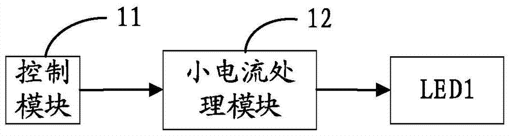
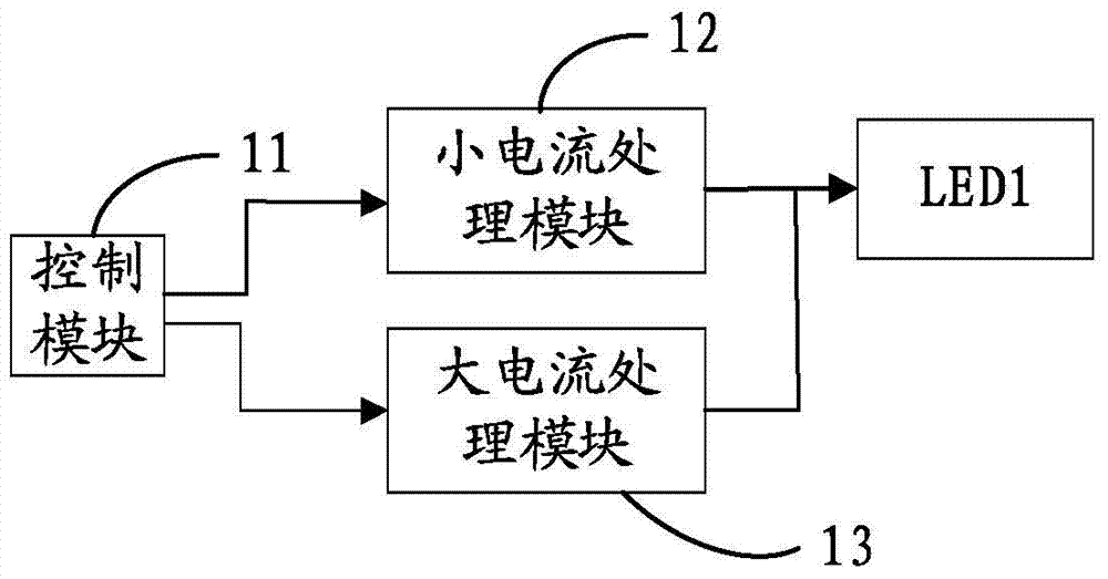
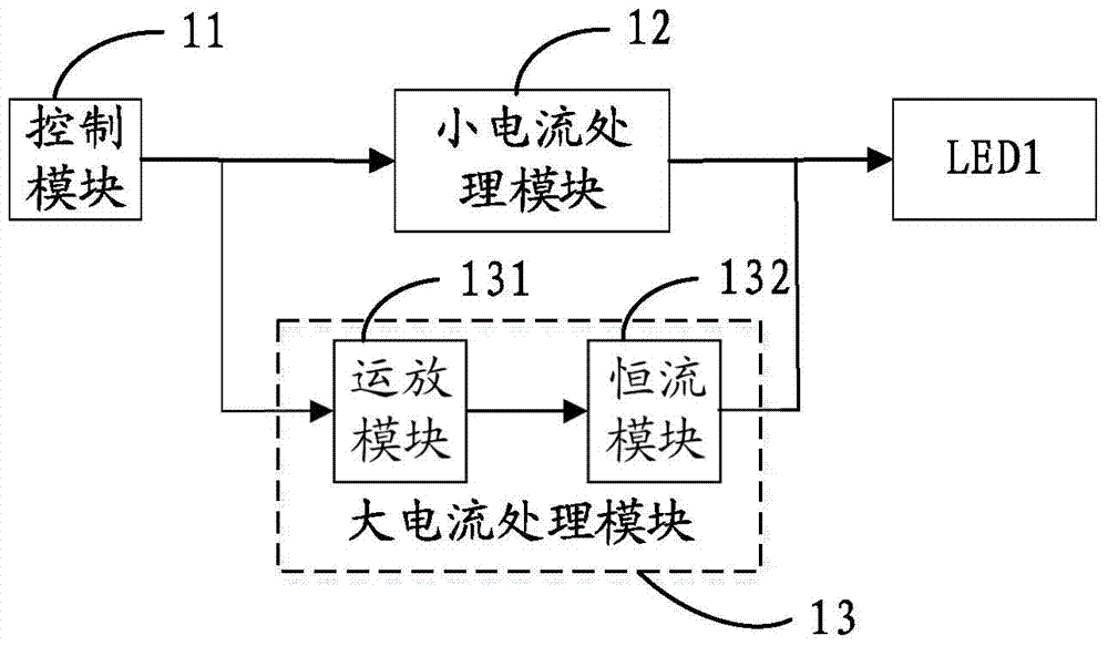
[0021] The specific embodiment of the present invention provides a stepless dimming circuit for controlling the lamp LED1, such as figure 1 As shown, the stepless dimming circuit includes a control module 11 and a small current processing module 12 connected to the control module 11, the output end of the small current processing module is connected to the anode of the lamp LED1, and the cathode of the lamp LED1 Grounded, wherein the control module 11 sends a small current PWM control signal to the small current processing module 12 when the current of the lamp LED1 is a small current, and the smal...


PUM


Abstract

The invention discloses a stepless dimming circuit, comprising a control module and a small current processing module connected with the control module, the output end of the small current processing module is connected with the anode of a lamp LED1, and the cathode of the lamp LED1 is grounded , wherein the control module sends a small current PWM control signal to the small current processing module when the current of the lamp LED1 is a small current, and the small current processing module outputs a signal according to the small current PWM control signal to control the light intensity of the lamp LED1 . When the current of the lamp LED1 is a small current, the control module can adjust the current output from the small current processing module to the lamp LED1 by controlling the duty ratio of the output small current PWM control signal, thereby realizing the adjustment of the light intensity of the lamp LED1, and adjusting It is smoother, makes the dimming process more uniform, reduces loss and improves efficiency at the same time, saves more power, and prolongs the service life of the lamp LED1.

Description

technical field [0001] The invention relates to a dimming circuit, in particular to a stepless dimming circuit for an LED lamp. Background technique [0002] The current LED dimming technology mainly realizes the adjustment of the power of the LED lamp by adjusting the resistance value of the potentiometer or controlling the frequency or conduction time of the switching tube. However, the loss of the two adjustment methods using the potentiometer or the switch tube will be relatively large, and the control is unstable, and it is easy to cause poor contact between the LED lamp and the gear position, and the efficiency is relatively low. The problem of uneven light process. [0003] Moreover, in the prior art, lamps and lanterns such as touch table lamps or hotel dimming lamps are controlled by high-voltage electricity, and high-voltage electricity has certain harm to the human body. In view of this, a new dimming technology is urgently needed to solve the existing problems. ...

Claims


Application Information

Patent Timeline
Patent Type & Authority Patents(China)
IPC IPC(8): H05B33/08H05B44/00
CPCH05B45/10
Inventor 丁柏平丁柏栋杨永平
Owner SHENZHEN ZHONGFUNENG ELECTRIC EQUIPMENG CO LTD
Why Eureka
Try Eureka