Novel adjustable ejector

An adjustable, ejector technology, applied in the direction of ejector, ejector, liquid ejector, etc., can solve the problems of single parameter, inability to adjust the structural parameters of ejector, and great influence on the performance of ejector refrigeration system, and achieve increased stability. sexual effect

Inactive Publication Date: 2016-03-02
彭光前
View PDF6 Cites 4 Cited by
  • Summary
  • Abstract
  • Description
  • Claims
  • Application Information

AI Technical Summary

Problems solved by technology

[0003] As the core component of the ejector refrigeration system, the structure of the ejector (such as the distance between the nozzle outlet and the inlet of the mixing chamber, the ratio of the cross-sectional area of ​​the nozzle outlet to the throat cross-sectional area, and the ratio of the cross-sectional area of ​​the mixing chamber to the throat cross-sectional area ratio) has a great influence on the performance of the ejector refrigeration system. However, the traditional ejectors are all fixed structures and are designed under a given working condition. Once manufactured, they can only be optimized under the designed working conditions However, it is difficult to maintain the working state of the system at the design working state under the actual working state, so once the working state of the generator, evaporator and condenser deviates from the design parameters, the performance of the ejector refrigeration system will decline
In order to enhance the applicability of the ejector and avoid or reduce the impact on the performance of the ejector refrigeration system due to changes in actual working conditions, people try to design an ejector with better adjustability, but the adjusted structural parameters are A single parameter, unable to adjust the structural parameters of the injector more comprehensively

Method used


Image

  • Novel adjustable ejector
  • Novel adjustable ejector
  • Novel adjustable ejector

Examples


Embodiment Construction

[0019] The present invention will be described in further detail below with reference to the accompanying drawings and specific embodiments.

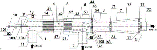
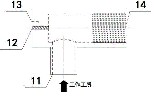
[0020] like figure 1 As shown, the nozzle 4 is connected to the working fluid inlet 1 and the suction chamber 5 through threads, and the direction of the two threads is the same. When adjusting the distance from the outlet of the nozzle 4 to the inlet of the mixing chamber 6, it is only necessary to rotate the nozzle 4 so that Axial movement does not need to change the relative position between the working fluid inlet 1 and the suction chamber 5. Therefore, the operation is simple and convenient. At the same time, there is a scale in the middle of the nozzle, which can easily read the nozzle 4 of the new adjustable injector. The distance from the outlet to the inlet of the mixing chamber 6. When the needle 81 of the distance measuring needle a8 points to L on the scale a42 1 scale value, it indicates that the new injector is in the de...


PUM


Abstract

The invention discloses a novel adjustable ejector. The ejector is composed of ten components including a working medium inlet, an injection working medium inlet end, a compressed working medium outlet, a nozzle, a suction chamber, a mixing chamber, a pressure expansion chamber, a distance measuring needle a, a distance measuring needle b and an adjusting cone. In order to facilitate adjustment and seal, all contact components are connected in a spiral manner. Through rotation of the nozzle and the adjusting cone, the axial position of the nozzle and the throat area of the nozzle can be adjusted, rulers are marked on the nozzle and the adjusting nozzle, and the distance between an outlet of the nozzle and an inlet of the mixed chamber can be obtained at any time through the distance measuring needles, and the throat area of the nozzle can be obtained at any time through the distance measuring needles. The novel adjustable ejector is simple in structure and convenient to operate; and stability of the performance of the ejector under the variable working condition can be enhanced, and the high adaptability is achieved.

Description

technical field [0001] The invention relates to a new type of adjustable injector, in particular to a nozzle that can adjust the axial position of the nozzle and the throat area of ​​the nozzle, and the nozzle and the adjustment cone are engraved with scales, and the nozzle can be obtained at any time through the distance measuring needle. The distance from the outlet to the inlet of the mixing chamber and the throat area of ​​the nozzle. The injector is an energy exchange device through which energy can be transferred from high-pressure fluid to low-pressure fluid. Background technique [0002] The ejector was first proposed by Parson in 1901. It is an energy exchange device. The ejector can transfer energy from high-pressure fluid to low-pressure fluid. It has the advantages of simple structure, reliable operation, and easy maintenance. [0003] As the core component of the ejector refrigeration system, the structure of the ejector (such as the distance between the nozzle ...

Claims


Application Information

Patent Timeline
Patent Type & Authority Applications(China)
IPC IPC(8): B05B7/04B05B1/32
Inventor 彭光前李苏泷李明胡昌群彭芳王蒙蒙
Owner 彭光前
Why Eureka
Try Eureka