
Winding facility for plastic wire and cable manufacturing

A wire and cable, plastic technology, applied in the field of winding equipment for plastic wire and cable manufacturing, can solve the problems of difficult adjustment, inconvenient cutting of plastic wire and cable, inconvenient removal of plastic wire and cable, etc., to achieve the effect of convenient disassembly and assembly

Inactive Publication Date: 2019-02-05
黄杰琦
View PDF0 Cites 3 Cited by
  • Summary
  • Abstract
  • Description
  • Claims
  • Application Information

AI Technical Summary

Problems solved by technology

[0004] The object of the present invention is to provide a kind of winding equipment for plastic wire and cable manufacturing, to solve the problem that the existing winding equipment for plastic wire and cable manufacturing proposed in the above background technology is often difficult to adjust during use, and the plastic wire cannot be well The cables are evenly wound on the winding equipment, it is inconvenient to remove the rewound plastic wires and cables, and it is inconvenient to cut the plastic wires and cables

Method used

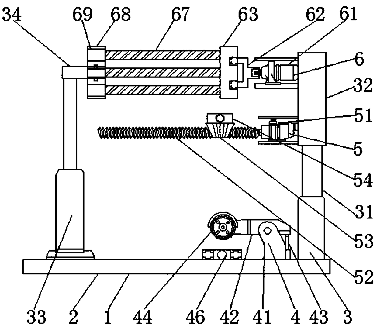
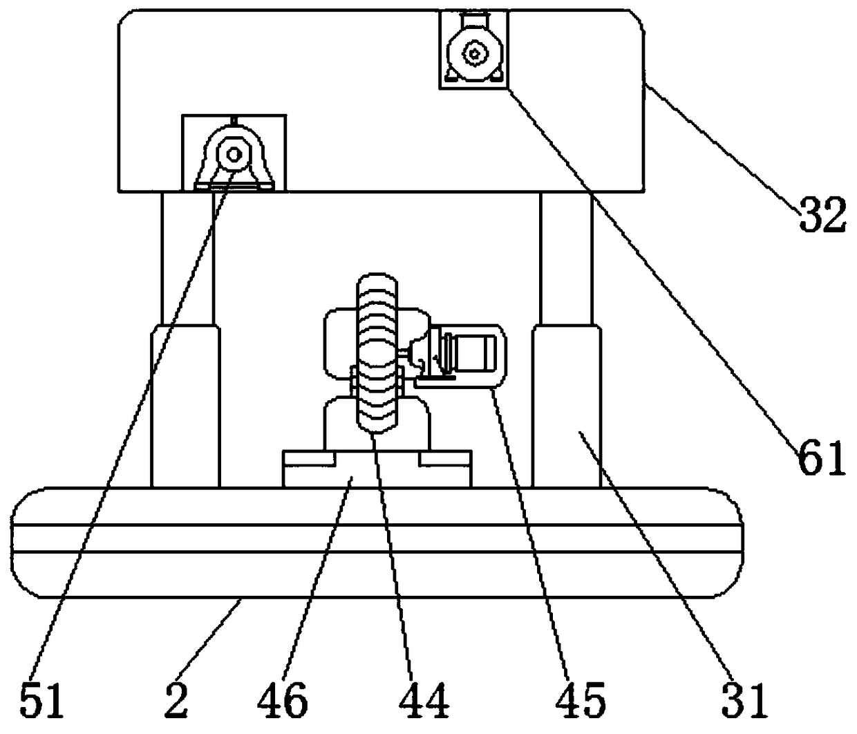
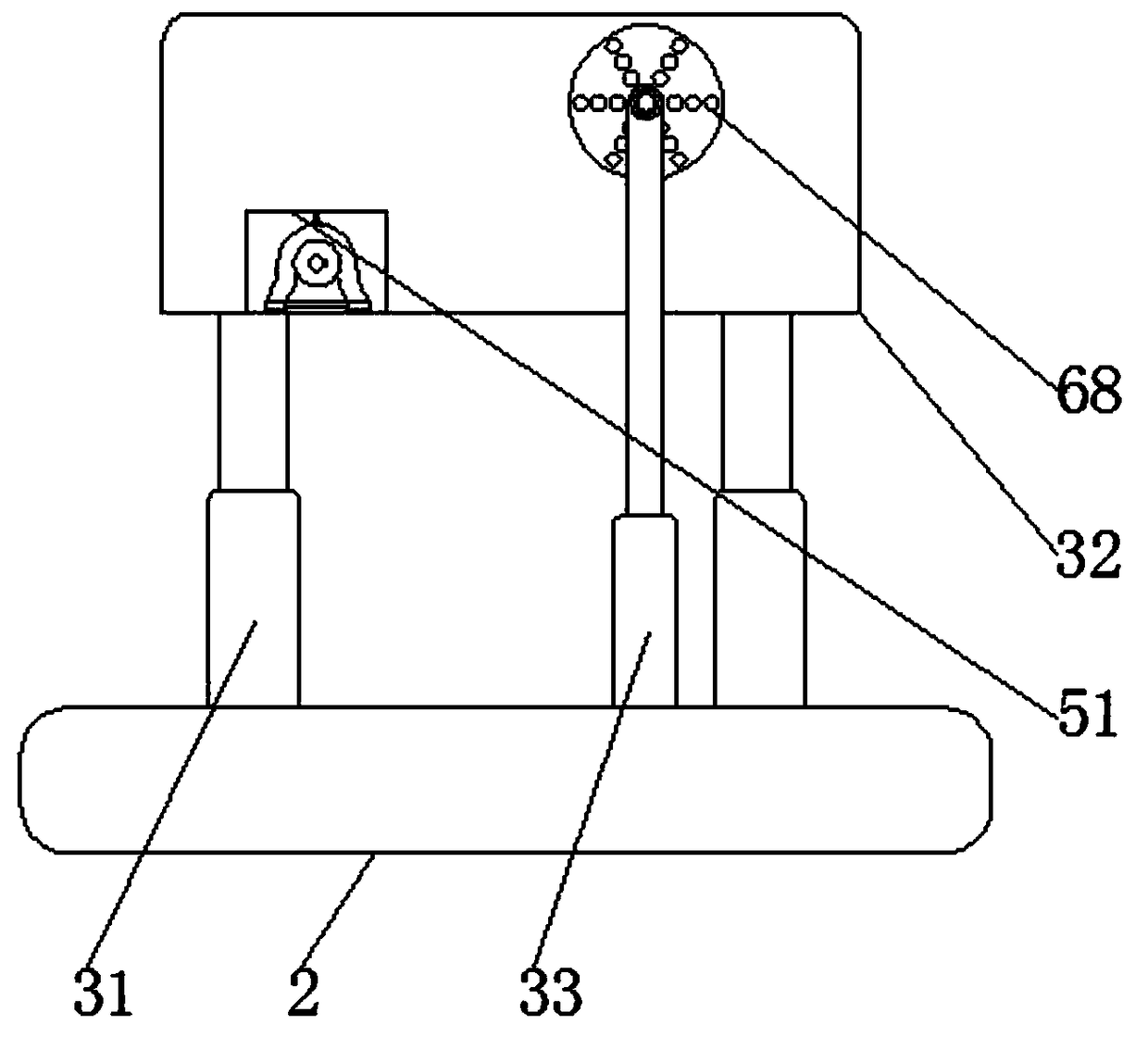

Image

  • Winding facility for plastic wire and cable manufacturing
  • Winding facility for plastic wire and cable manufacturing
  • Winding facility for plastic wire and cable manufacturing

Examples


Embodiment Construction

[0030] In order to enable those skilled in the art to better understand the technical solution of the present invention, the present invention will be described in detail below in conjunction with the accompanying drawings. The description in this part is only exemplary and explanatory, and should not have any limiting effect on the protection scope of the present invention. .

[0031] Such as Figure 1-Figure 7 As shown, the specific structure of the present invention is: a winding device for plastic wire and cable manufacturing, including a body 1, a base 2, a lifting mechanism 3, a cutting mechanism 4, a wire harness mechanism 5 and a winding mechanism 6, the body 1 The base 2 is installed on the bottom, and the lifting mechanism 3 and the cutting mechanism 4 are installed on the base 2. The wire harness mechanism 5 is installed on the side away from the lifting mechanism 3 of the base 2, and the wire harness mechanism 5 is installed on the side away from the base 2. There...


PUM


Abstract

The invention relates to a winding facility for plastic wire and cable manufacturing. The winding facility for plastic wire and cable manufacturing comprises a machine body, a base, a lifting mechanism, a cutting mechanism, a wire bundling mechanism and a winding mechanism. The base is installed at the bottom of the machine body. The lifting mechanism and the cutting mechanism are installed on thebase, the wire bundling mechanism is installed on the side far away from the lifting mechanism on the base, and the winding mechanism is installed on the side far away from the wire bundling mechanism on the base. After operation of the winding facility for plastic wire and cable manufacturing is accomplished, a connecting plate can be moved, through holes in the connecting plate and wire windingrods can be separated, and therefore the connecting plate moves to one end of an insertion rod, a second hydraulic rod is opened, the insertion rod, a bearing and the connecting plate downwards movealong with the second hydraulic rod under the action of the second hydraulic rod, the bearing sleeves the insertion rod, electric telescoping rods are opened, and insertion grooves can carry the wirewinding rods to move under the action of the electric telescoping rods. In this way, cables which are wound can be better separated from the wire winding rods, the cables which are well wound can be well taken down, and therefore the follow-up packaging operation is conducted on the cables.

Description

technical field [0001] The invention relates to the field of plastic wire and cable manufacturing equipment, in particular to a winding device for plastic wire and cable manufacturing. Background technique [0002] Electricity is an indispensable resource in human life. With the progress of human life, people are increasingly inseparable from electricity, and plastic wires and cables are indispensable in the process of electricity transportation. [0003] Due to the rapid development of power equipment, its related equipment is also developing rapidly, among which plastic wires and cables have also been developed rapidly. Plastic wires and cables often need to be reeled after manufacture, and most of the reeling of plastic wires and cables on the market is manual. The efficiency is low, and the few winding equipment for mechanical plastic wire and cable manufacturing are often difficult to adjust during use, and the plastic wire and cable cannot be evenly wound on the windin...

Claims


Application Information

Patent Timeline
Patent Type & Authority Applications(China)
IPC IPC(8): B65H54/28B65H67/04
CPCB65H54/28B65H67/04B65H2701/34
Inventor 黄杰琦黄少邱
Owner 黄杰琦
Learn More