Method with low-voltage field transmission electronic source

A field emission and electron source technology, applied in the field of electron sources, can solve the problems of large volume, short service life and high energy consumption, achieve the effect of large aspect ratio, excellent field emission performance, and increase field emission current density

Inactive Publication Date: 2004-12-08
INST OF METAL RESEARCH - CHINESE ACAD OF SCI
View PDF0 Cites 4 Cited by
  • Summary
  • Abstract
  • Description
  • Claims
  • Application Information

AI Technical Summary

Problems solved by technology

Due to the shortcomings of large volume, high energy consumption, and short service life, traditional thermal emission electron sources can no longer meet the needs of modern technological development.

Method used


Image

  • Method with low-voltage field transmission electronic source
  • Method with low-voltage field transmission electronic source
  • Method with low-voltage field transmission electronic source

Examples


Embodiment 1

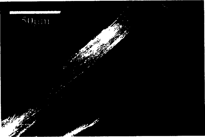
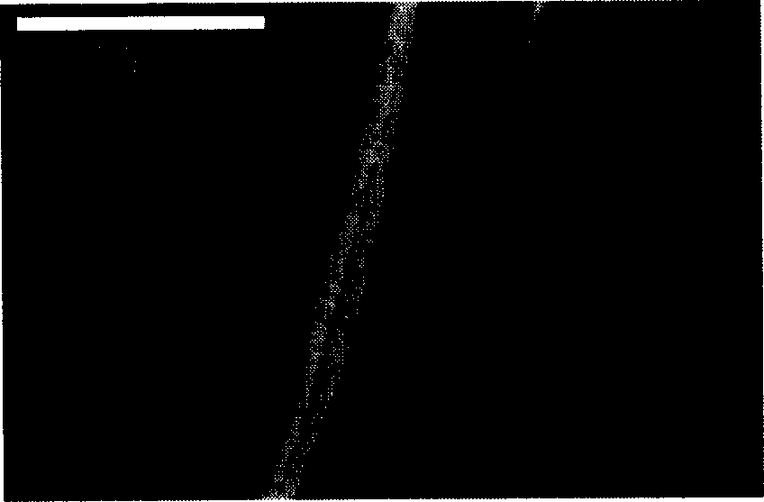
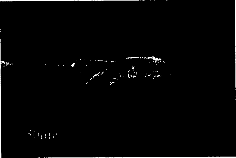
[0025] The method of the present invention adopts copper mesh grid, with a single rope-like single-walled carbon nanotube as the field emission cathode, the diameter is about 80 μm, and the effective length of the sample is about 2mm; it is fixed on the conductive substrate as a sample, so that the sample The axis direction is perpendicular to the substrate surface; control the vacuum to 2×10 -7 After Pa, apply an external voltage of 1000V between the field emission cathode and the pressurized anode, and the distance between the pressurized anode and the cathode is 1mm, and a part of the obtained field emission electrons pass through the pressurized anode to obtain an effective field emission current.

[0026] Among them, the preparation of rope-like single-wall carbon nanotubes: the preparation of rope-like single-wall carbon nanotubes with macroscopic length (centimeter level) by hydrogen arc method: the graphite disc surface as the anode is processed with 5 round holes, and ...

Embodiment 2

[0029] The difference from Example 1 is that the effective length of a single rope-like single-wall carbon nanotube sample is about 15mm, the distance between the pressurized anode and the cathode is 0.1mm, and the vacuum degree of the system is 2×10 -8 Pa. Applying an external voltage of 250V, the available effective field emission current I 1 More than 30μA; effective field emission current I 1 The ratio with the total field emission current I is determined by the opening ratio of the copper mesh grid, for the present embodiment 2, I 1 / I>60%. Calculate the field emission threshold of the carbon tube rope (the emission current density reaches 10mA / cm 2 When the applied electric field) is 0.01V / μm.

Embodiment 3

[0031] The difference from Example 1 is:

[0032] The working vacuum of the field emission electron gun of a single rope-shaped single-walled carbon nanotube is 3×10 -3 Pa, applying an external voltage of 700V, the available effective field emission current I 1 More than 30μA; effective field emission current I 1 The ratio with the total field emission current I depends on the opening ratio of the copper mesh grid, for the present embodiment 3, I 1 / I>60%. Calculate the field emission threshold of the carbon tube rope (the emission current density reaches 10mA / cm 2 When the applied electric field) is 0.09V / μm.


PUM

PropertyMeasurementUnit
Diameteraaaaaaaaaa

Abstract

In the invention, copper mesh grid or sheet copper having holes is as anode with voltage applied. Funicular nano carbon tubes are as field emission cathode. Material of cathode emission is fixed on current conducting substrate, and axis direction of specimen is perpendicular to surface of substrate. Distance between anode and cathode is 0.1- l mm. Operating vacuum degree is controlled at region 1X10⁻³ - 1X10 -8 Pa, and voltage at 0.2-3 kV is applied between anode and cathode. Part of electrons of field emission is able to passing through anode so as to obtain field emission current in low voltage. Features of the invention are: outstanding performances of field emission, operability and operating at low voltage. Under condition of voltage not higher than lkV, field emission current is in tens microampere, and largest reaches to hundreds microampere.

Description

technical field [0001] The invention relates to an electron source, in particular to a method for assembling a low-voltage field emission electron source. Background technique [0002] Electron sources, also known as electron guns, have important applications in the fields of electron microscopy, video display technology, X-ray tubes, and light-emitting elements. Due to the shortcomings of large volume, high energy consumption, and short service life, traditional thermal emission electron sources cannot meet the needs of modern technology development. As one of the main products for replacement, the cold cathode field emission electron source has the advantages of low energy consumption, long emission life, and high emission intensity. It is expected to replace the thermal emission electron source and become the mainstream product of the next generation in the near future. [0003] Traditional field emission cathode materials mainly include titanium (Ti), molybdenum (Mo), t...

Claims


Application Information

Patent Timeline
IPC IPC(8): H01J9/02H01J9/18
Inventor 成会明佟钰刘畅赵志刚
Owner INST OF METAL RESEARCH - CHINESE ACAD OF SCI
Why Eureka
Try Eureka