A-frame luffing mechanism and control system thereof
A technology of luffing mechanism and control system, which is applied in the direction of fluid pressure actuated system components, cranes, mechanical equipment, etc., can solve the problems of unstable luffing process, poor use efficiency and safety performance, etc. Stable, guaranteed synchronization and safety, stable amplitude effect
- Summary
- Abstract
- Description
- Claims
- Application Information
AI Technical Summary
Problems solved by technology
Method used
Image


Examples
Embodiment 1
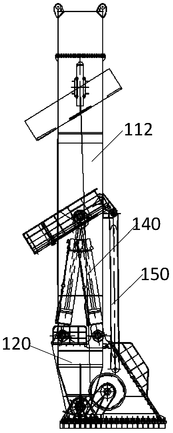
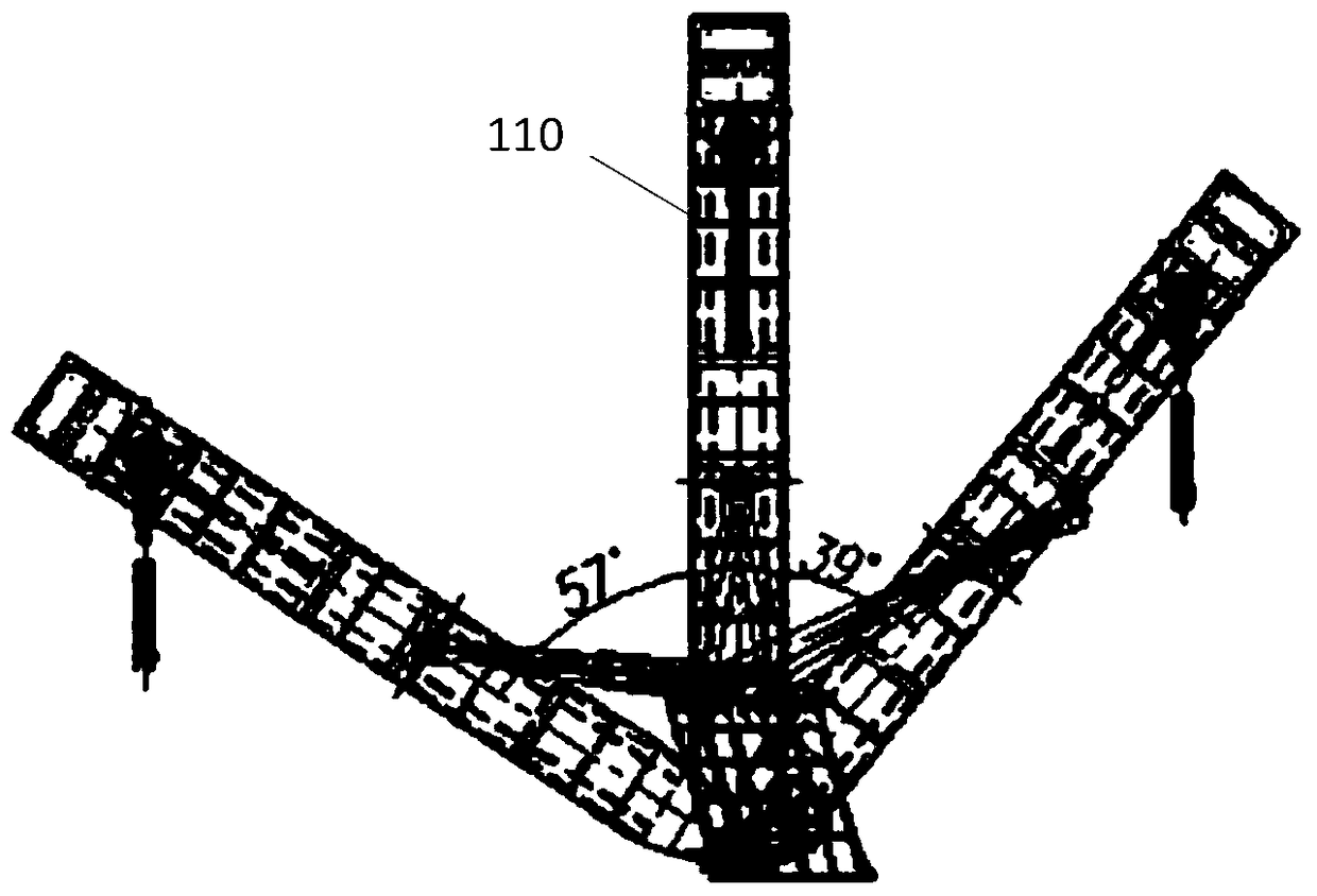
[0042] In order to solve the technical problems in the prior art that the luffing process of the control system of the A-frame is not stable, and the use efficiency and safety performance are poor, the application provides an A-frame luffing mechanism. Such as figure 1 , figure 2 and image 3 As shown, the A-frame luffing mechanism includes a portal frame 110, an oil cylinder support 120, two first luffing cylinders 130, two second luffing cylinders 140 and a control system.
[0043] The portal frame 110 includes a beam 111 and two uprights 112 fixedly connected to both ends of the beam 111 , and the two uprights 112 are pivotally connected to a base (not shown).
[0044] The oil cylinder support 120 is fixed on the base.
[0045] One ends of the two first luffing cylinders 130 and the two second luffing cylinders 140 are fixed on the cylinder support 120 , and the other ends of the two first luffing cylinders 130 and the two second luffing cylinders 140 The other ends of...
Embodiment 2
[0084] Based on the same inventive concept, the present application also provides a control system of the A-frame luffing mechanism, the control system adopts an open system, and the control method adopts electronic control (closed-loop control, through the control signal, the oil cylinder position sensor signal and the area The signal is automatically completed), the reversing method adopts valve control, and the speed regulation method adopts pump control. exist Figure 4 Among them, the left A luffing cylinder and the left B luffing cylinder are the first luffing cylinder 130 , and the right A luffing cylinder and right B luffing cylinder are the second luffing cylinder 140 .
[0085] Such as Figure 4 As shown, the control system includes a main circuit one and a main circuit two, and the main circuit one mainly supplies oil to the left cylinder group.
[0086] Main circuit 1 includes: oil pump 1, oil pump 2, two butterfly valves 18, two oil suction filters 15, two first...
PUM
 Abstract
Description
Claims
Application Information
 - R&D
- Intellectual Property
- Life Sciences
- Materials
- Tech Scout
- Unparalleled Data Quality
- Higher Quality Content
- 60% Fewer Hallucinations
Browse by: Latest US Patents, China's latest patents, Technical Efficacy Thesaurus, Application Domain, Technology Topic, Popular Technical Reports.
© 2025 PatSnap. All rights reserved.Legal|Privacy policy|Modern Slavery Act Transparency Statement|Sitemap|About US| Contact US: help@patsnap.com