
Distributing adjusting mechanism for heat treatment furnace

A heat treatment furnace, split flow adjustment technology, applied in the field of heat treatment furnace split flow adjustment mechanism, can solve the problems of not being able to ensure metal objects, affecting heat treatment effects, etc.

Inactive Publication Date: 2016-03-02
重盈阳成工业股份有限公司
View PDF3 Cites 0 Cited by
  • Summary
  • Abstract
  • Description
  • Claims
  • Application Information

AI Technical Summary

Problems solved by technology

[0004] However, at present, after the metal object passes through the heat treatment furnace to complete a procedure, the object is directly sent out from the discharge port of the heat treatment furnace, and then a single collection device is used to enable the object to enter the next procedure. Some are dry heat treatment, and some are wet heat treatment. Therefore, after a metal object completes a heat treatment process, some objects are in a dry state, and some are in a wet state. Now, a single collection device is installed at the discharge port If the first batch of wet objects is conveyed and the latter batch of dry objects is conveyed, if there is water stains on the collecting device, it will adhere to the surface of the objects, which will affect the effect of heat treatment
[0005] Therefore, in view of the fact that a single collection device is installed at the discharge port of the current heat treatment furnace, and there is a problem derived from the dry and wet lanes, the inventors thought that if multiple collection devices can be connected at the discharge port, so that Metal objects that have completed different procedures enter different collection devices to achieve the purpose of dry and wet lane separation. However, simply installing multiple collection devices at the discharge port cannot ensure that the metal objects after heat treatment will indeed fall into the set Collecting device, so the inventor has developed a complete set of shunt adjustment mechanism

Method used


Image

  • Distributing adjusting mechanism for heat treatment furnace
  • Distributing adjusting mechanism for heat treatment furnace
  • Distributing adjusting mechanism for heat treatment furnace

Examples


Embodiment Construction

[0049] In order to have a clearer understanding of the technical features, purposes and effects of the present invention, the specific implementation manners of the present invention will now be described with reference to the accompanying drawings.

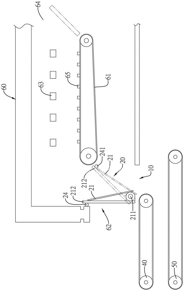
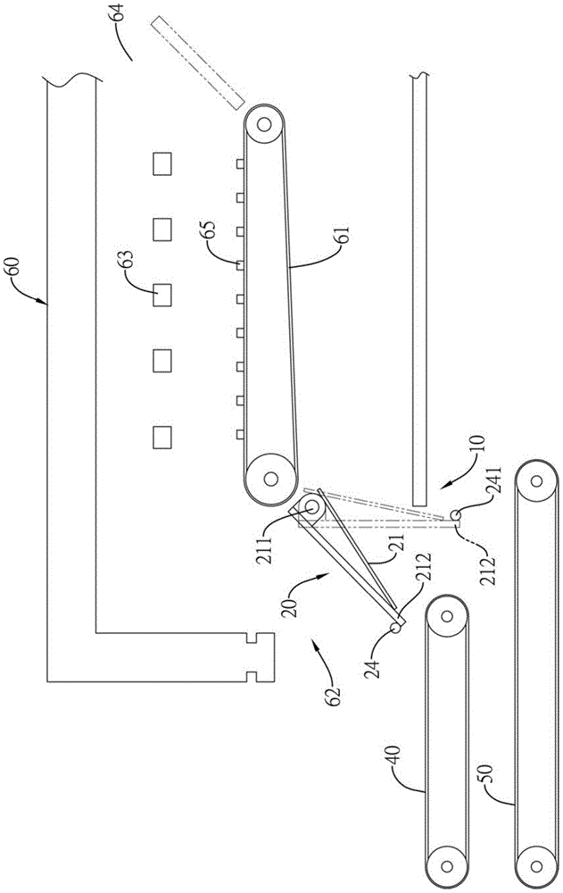
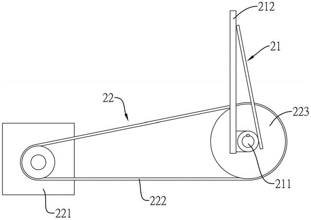
[0050] The diversion adjustment mechanism of the present invention mainly includes a diversion device and a plurality of collection devices, wherein the diversion device is arranged between the conveyor belt inside the heat treatment furnace and the discharge port, and the plurality of collection devices are arranged at the discharge of the heat treatment furnace At the outlet, the objects that have completed the heat treatment process in the heat treatment furnace are diverted to a specific collection device through a diversion device, and the above-mentioned technical features can have various implementation forms, wherein the diversion device can be further a rotary diversion device, or It is a translational diversion device. T...


PUM


Abstract

The invention relates to a distributing adjusting mechanism for a heat treatment furnace. The distributing adjusting mechanism comprises a distributing mechanism arranged in the heat treatment furnace and between a conveying belt and a discharging port, and a plurality of collecting devices located at the discharging port of the heat treatment furnace. The distributing device can be a rotating type distributing device or a horizontal-moving distributing device. According to the distributing adjusting mechanism for the heat treatment furnace, articles on which heat treatment is completed are distributed to the collecting devices, and therefore the articles on which heat treatment is completed are indeed distributed, and the heat treatment effect of the articles cannot be affected.

Description

technical field [0001] The invention relates to a heat treatment furnace split flow regulating mechanism, in particular to a heat treatment furnace split flow regulating mechanism which is arranged at the outlet of the heat treatment furnace and can perform flow splitting. Background technique [0002] In addition to the characteristics of the material itself, general metal objects will change the characteristics of the material with the help of heat treatment procedures. The most common heat treatment methods are annealing, quenching, tempering and normalization, and each heat treatment method is further subdivided into many A treatment method whereby the heat-treated object obtains its required characteristics. [0003] Therefore, before the heat treatment process, the process must be set according to the original material properties of the metal object and the properties to be obtained. Therefore, in addition to setting a temperature-adjustable heating device in the heat ...

Claims


Application Information

Patent Timeline
IPC IPC(8): C21D1/00
Inventor 曾柏华
Owner 重盈阳成工业股份有限公司
Learn More