Disc brake assembly

A technology of disc brakes and brake discs, applied in the direction of brake types, brake components, gear transmission mechanisms, etc., can solve the problems of high manufacturing cost, consumption, and consumption design

Inactive Publication Date: 2016-03-02
ZF FRIEDRICHSHAFEN AG
View PDF6 Cites 0 Cited by
  • Summary
  • Abstract
  • Description
  • Claims
  • Application Information

AI Technical Summary

Problems solved by technology

[0006] The known disc brake is structurally complex, requiring not only a considerable installation space but also high manufacturing costs
Cost-intensive and maintenance-intensive braking device due to structurally complex mounting of the pivoting element

Method used


Image

  • Disc brake assembly

Examples


Embodiment Construction

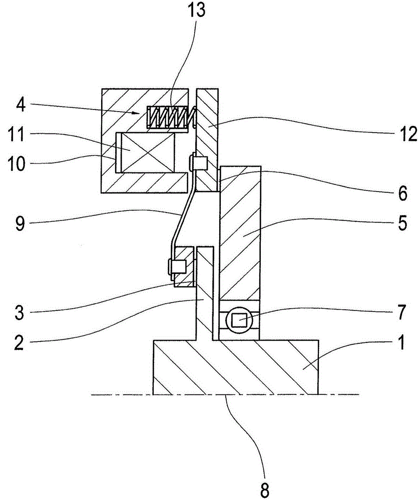
[0016] In the embodiment variant shown, a single-sided brake is shown. However, it is conceivable to use double-sided brakes or multi-disk brakes. Independent of the corresponding brake design used, this type of brake has the advantage that maintenance-free operation is ensured over the entire service life of the drive system.

[0017] The disc brake mechanism or disc brake is used to apply a predetermined braking torque depending on the direction of rotation in order to decelerate the shaft 1 . The disc brake mechanism comprises a first brake disc 2 connected in a rotationally fixed manner to the shaft 1 and at least one associated first friction surface 3 , which can be activated via a brake actuating device 4 for applying a desired braking torque. Connection (Wirkverbindung).

[0018] According to the invention it is provided that at least one second brake disk 5 is provided with at least one second friction surface 6 , wherein the braking torque transmittable to the seco...


PUM


Abstract

Disclosed is a disc brake assembly for rotational direction-dependent applying a predetermined braking torque for braking a shaft (1) having a first brake disc (2) and with at least one associated first friction surface (3) in a brake actuator (4) for applying a desired braking torque operative connection can be brought, at least a second brake disc (5) and at least a second friction surface (6) are provided, wherein the on the second brake disc (5) transferable braking torque is dependent on the direction of rotation transmitted to the shaft (1).

Description

technical field [0001] The present invention relates to a disc brake mechanism for applying a predetermined braking torque depending on the direction of rotation for decelerating a shaft. Background technique [0002] Disc brakes are used, for example, in vehicles in order to apply a predetermined braking torque to the drive wheels as required in order to slow or stop the vehicle. In this case, the same braking torque is applied regardless of the direction of rotation of the drive wheels. [0003] For example, in drive systems of escalators, moving walks or the like it is required that the braking device exerts a braking torque which is dependent on the direction of rotation. This is because the escalator / moving walk can be driven in both directions and eg driving the escalator / moving walk upwards requires less braking torque than driving the escalator / moving walk downwards. Thus, the braking torque applied depending on the direction of rotation prevents injuries or falls ...

Claims


Application Information

Patent Timeline
Patent Type & Authority Applications(China)
IPC IPC(8): F16D55/02B66D5/14
CPCB66D5/14F16D65/186F16D2121/22F16D2127/005
Inventor 伊尔亚·伊米格伦特
Owner ZF FRIEDRICHSHAFEN AG
Why Eureka
Try Eureka