Connecting structure of shaft-mounted brake disc and disc hub of railway vehicle

A rail vehicle and brake disc technology, applied in the direction of brake discs, brake components, brake types, etc., can solve problems such as reducing service life and affecting the safety of brake discs in service

Active Publication Date: 2016-03-02
BEIJING JIAOTONG UNIV
View PDF6 Cites 8 Cited by
  • Summary
  • Abstract
  • Description
  • Claims
  • Application Information

AI Technical Summary

Problems solved by technology

During the braking and cooling process, the brake disc body will expand and contract due to drastic temperature changes, and then a large internal stress will be formed inside the disc body and at the connection between the brake disc and the hub, affecting braking. Disk service safety and reduce its service life

Method used


Image

  • Connecting structure of shaft-mounted brake disc and disc hub of railway vehicle
  • Connecting structure of shaft-mounted brake disc and disc hub of railway vehicle
  • Connecting structure of shaft-mounted brake disc and disc hub of railway vehicle

Examples


Embodiment Construction

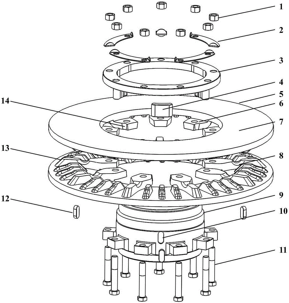
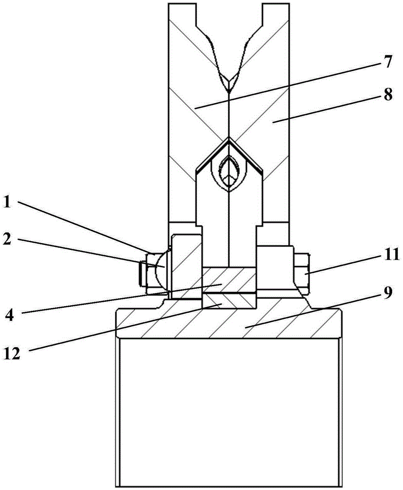
[0018] The connection between a rail vehicle shaft-mounted brake disc and the disc hub is shown in the appendix figure 1 , a rail vehicle shaft-mounted brake disc, comprising a hub (9), a disc body (7) and a disc body (8), the disc body is composed of a flange (6), a friction ring (5), a cooling rib (13) Form a whole.

[0019] A rail vehicle shaft-mounted brake disc, which adopts a spliced ​​disc structure, and a complete set of brake discs includes identical disc bodies (7) and disc bodies (8), all of which are made of low-alloy forged steel materials and formed into The way is forging. The height of the disc body after assembly is 80mm.

[0020] The friction ring (5) of the disc body (7, 8) has a thickness of 22 mm, an outer diameter of 640 mm, and an inner diameter of 350 mm.

[0021] The flange (6) has 10 Φ28mm through-holes evenly distributed in the circumferential direction, and 3 pairs of U-shaped grooves (14) are evenly distributed in the circumferential direction b...


PUM


Abstract

The invention discloses a shaft-mounted brake disc of a railway vehicle. The structure of a disc body (7) is the same as the structure of a disc body (8). The disc bodies form a whole through flanges (6), friction rings (5) and radiation ribs (13). Through holes are evenly distributed in the circumferential direction of each flange (6). The radiation ribs (13) are evenly distributed in the circumferential direction. Through holes are evenly distributed in the circumferential direction of a disc hub (9), and the number of the through holes is the same as the number of the through holes in the flanges (6). U-shaped grooves (14) are evenly distributed in the flanges (6) of the disc body (7) and the flanges (6) of the disc body (8) in the circumferential direction, and after the disc body (7) and the disc body (8) are buckled, circumferential fixing can be achieved by press fitting of pressing blocks (4) into the U-shaped grooves (14). Key grooves (10) are evenly distributed in the circumferential direction of the disc hub (9), the pressing blocks (4) are provided with through grooves (15), and the number of the pressing blocks (4) and the number of the U-shaped grooves (14) are the same as the number of the key grooves (10) in the disc hub (9). When the disc body (7) and the disc body (8) are installed on the disc hub (9), centering and circumferential positioning of the disc body (7) and the disc body (8) together with the disc hub (9) are achieved through the matching of the through grooves (15) in the pressing blocks (4) and positioning keys (12). Fastening bolts (11) sequentially penetrate through the disc hub (9), the disc body (8), the disc body (7), a pressing ring (3) and gaskets (2), and the disc hub (9), the disc body (7) and the disc body (8) can be fixed in the axial direction by connecting nuts (1) and the fastening bolts (11). The problems that an existing brake disc body and a disc hub are staggered and the brake torque can only be transmitted through friction force are solved.

Description

technical field [0001] The invention relates to the technical field of rail vehicle disc brakes, in particular to a connection structure between a rail vehicle shaft-mounted brake disc and a disc hub. technical background [0002] With the increase of train speed, urban express trains with a speed of more than 120km per hour, fast heavy-duty trucks with a speed of 160km per hour, EMUs and high-speed trains with a speed of more than 200km per hour have all adopted disc brakes. The brake disc is the basic brake element of the disc brake, which converts the kinetic energy of the train into heat energy through friction with the brake pads and dissipates it in the atmosphere. [0003] At present, rail vehicles at home and abroad use iron, steel, aluminum-based composite materials, and C / C composite materials as brake disc materials, and steel materials as brake disc materials have high technical maturity, low cost, and are applicable. The characteristics of wide speed range have...

Claims


Application Information

Patent Timeline
Patent Type & Authority Applications(China)
IPC IPC(8): F16D65/12
CPCF16D65/124F16D2065/1384
Inventor 杨智勇韩建民李志强吴雷李卫京王金华
Owner BEIJING JIAOTONG UNIV
Why Eureka
Try Eureka