Constant-temperature valve element structure

A thermostatic valve core and valve core technology, applied in valve details, multi-port valves, valve devices, etc., can solve problems such as large water entry obstacles, stuck impurities, and poor sealing, shortening waterways, reducing components, and costs. reduced effect

Inactive Publication Date: 2016-03-02
王金鹤
View PDF0 Cites 3 Cited by
  • Summary
  • Abstract
  • Description
  • Claims
  • Application Information

AI Technical Summary

Problems solved by technology

In practical application, this part has defects such as easy to be stuck by

Method used


Image

  • Constant-temperature valve element structure

Examples


Embodiment Construction

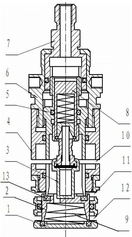
[0015] Referring to the accompanying drawings, the present invention includes a valve core lower sleeve 1, a middle sleeve 4, an adjustment slider 5 and an adjustment knob 7, and the valve core lower sleeve 1 is provided with a cold water inlet port 11 and a hot water inlet port 12. The hot water inlet port 12 is located at the bottom of the lower sleeve 1 of the valve core, and the cold water inlet port 11 is located at the upper part of the lower sleeve 1 of the valve core. The lower sleeve 1 is connected by threads, and a mixed water outlet port 10 is provided on the bottom side of the middle sleeve. Spool lower cover 1 is provided with a moving slider 2, and the bottom half inner chamber device big spring 9 of moving slider 2, the lower plane of big spring contacts with the bottom plane of spool lower cover 1. The lower plane of the sliding block 2 is sealed with the bottom of the valve core lower cover 1 by a rubber pad.

[0016] The adjusting slider 5 is located in the ...


PUM


Abstract

The invention relates to a constant-temperature valve element structure. The constant-temperature valve element structure comprises a valve element lower sleeve, a middle sleeve, an adjusting sliding block and an adjusting rotary knob. A hot water inlet port and a cold water inlet port are formed in the valve element lower sleeve, the hot water inlet port is formed in the bottom of the valve element lower sleeve, and the cold water inlet port is formed in the upper portion of the valve element lower sleeve; the middle sleeve is located on the upper portion of the valve element lower sleeve, the middle sleeve is in threaded connection with the valve element lower sleeve, a mixed water outlet port is formed in the side face of the bottom of the middle sleeve, and a movable sliding block is arranged in the valve element lower sleeve; the lower plane of the movable sliding block and the bottom of the valve element lower sleeve are sealed through a rubber pad, an upper sleeve is arranged above the middle sleeve, and an adjusting sliding block is located in the upper sleeve; and sealing is achieved in the manner that the lower face of the adjusting sliding block is pressed on and embedded into the plane of the upper portion of the movable sliding block, and a temperature sensing element is arranged on the upper portion of the movable sliding block. Constant-temperature adjustment can be achieved through one temperature adjusting handle, and cold and hot water entering the valve element can be synchronously started and stoppe.

Description

technical field [0001] The invention relates to a hot and cold water valve core, in particular to a constant temperature valve core structure. Background technique [0002] With the development of society, people have higher and higher requirements for life. The existing thermostatic valve core does not control the water in and out, but only adjusts the flow rate of cold and hot water entering the valve core. When assembled in the thermostatic shell, An additional switch is required to control the water flow; in addition, the existing thermostatic valve core generally enters hot and cold water from a place close to the temperature adjustment handle, and flows water in a direction away from the temperature adjustment handle. This determines that the thermostatic valve body needs to be installed in parallel with the wall of the fixed valve, so that the waterway setting of the thermostatic valve body is more complicated and the valve body is relatively bulky. Most of the therm...

Claims


Application Information

Patent Timeline
IPC IPC(8): F16K11/20F16K31/44F16K31/64
Inventor 王金鹤
Owner 王金鹤
Why Eureka
Try Eureka