Switch seat body structure and manufacturing method thereof

a technology of switch seat and manufacturing method, which is applied in the direction of emergency casings, electrical equipment, emergency protective devices, etc., can solve the problems of troublesome and time-consuming manufacturing and processing procedures and the cost of conventional switch seat bodies is higher, so as to facilitate manufacturing, simplify the structure of switch seat bodies, and enhance the resistance of switch seat bodies

Active Publication Date: 2018-01-16
SWITCHLAB +1
View PDF3 Cites 1 Cited by
  • Summary
  • Abstract
  • Description
  • Claims
  • Application Information

AI Technical Summary

Benefits of technology

[0010]It is therefore a primary object of the present invention to provide a switch seat body structure and a manufacturing method thereof. The switch seat body structure is simplified and can be easily manufactured to enhance the resistance of the switch seat body against the external damaging force. The switch seat body structure includes a main body for assembling with an internal component of the switch. The main body is an assembly of a metal head section and a nonmetal belly section. The metal head section has a shoulder section, a skirt section connected with the shoulder section and a subsidiary shoulder section formed on the skirt section. The nonmetal belly section is overlaid and connected on at least a part of the skirt section or the entire skirt section, whereby the nonmetal belly section is connected with subsidiary shoulder section to form an integrated structure. The manufacturing and processing procedure of the conventional switch seat body is troublesome and time-consuming. As a result, the cost for the conventional switch seat body is higher. The switch seat body structure of the present invention overcomes the problems existing in the conventional switch seat body.

Problems solved by technology

The manufacturing and processing procedure of the conventional switch seat body is troublesome and time-consuming.
As a result, the cost for the conventional switch seat body is higher.

Method used


Image

  • Switch seat body structure and manufacturing method thereof
  • Switch seat body structure and manufacturing method thereof
  • Switch seat body structure and manufacturing method thereof

Examples


Embodiment Construction

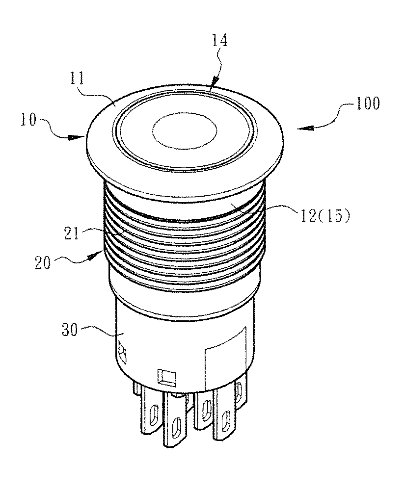
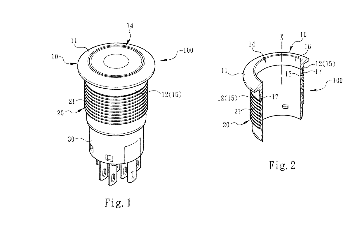
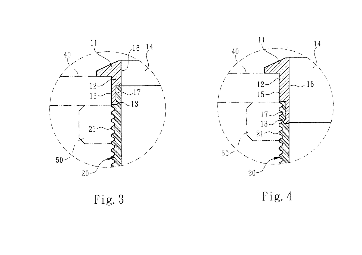
[0020]Please refer to FIGS. 1, 2 and 3. The switch seat body structure of the present invention includes a switch seat main body 100. The main body 100 is assembled with an internal component 30 of the switch to forma switch device or switch assembly. In this embodiment, the main body 100 is an assembly of a metal head section 10 and a nonmetal belly section 20. The metal head section 10 has a shoulder section 11, a skirt section 12 connected with the shoulder section 11 and a subsidiary shoulder section 13 formed on the skirt section 12. The shoulder section 11 and the skirt section 12 together define a shaft hole 14 and an axis χ. The shoulder section 11 outward protrudes from the metal head section 10. The skirt section 12 is substantially normal to the shoulder section 11 and downward extends from the shoulder section 11 in the direction of the axis χ (along the nonmetal belly section 20). The subsidiary shoulder section 13 is formed at a free end of the skirt section 12 and pro...


PUM

PropertyMeasurementUnit
poweraaaaaaaaaa
transparentaaaaaaaaaa
structural hardnessaaaaaaaaaa

Abstract

A switch seat body structure and a manufacturing method thereof. The switch seat body structure is simplified and can be easily manufactured to enhance the resistance of the switch seat body against the external damaging force. The switch seat body structure includes a main body for assembling with an internal component of the switch. The main body is an assembly of a metal head section and a nonmetal belly section. The metal head section has a shoulder section, a skirt section connected with the shoulder section and a subsidiary shoulder section formed on the skirt section. The nonmetal belly section is overlaid and connected on at least a part of the skirt section or the entire skirt section, whereby the nonmetal belly section is connected with subsidiary shoulder section to form an integrated structure.

Description

BACKGROUND OF THE INVENTION[0001]1. Field of the Invention[0002]The present invention relates generally to a switch seat body structure and a manufacturing method thereof, and more particularly to a switch seat body structure including a metal head section and a nonmetal belly section. The nonmetal belly section is overlaid on and integrally connected with the metal head section to form the switch seat body structure.[0003]2. Description of the Related Art[0004]A conventional switch or switch indication device is applied to electrical mechanism, electronic apparatus and auto-control system for an operator to know the operation or power on / off state of the machine. The conventional switch device includes a seat body or main body, an internal component and multiple sets of terminal pins arranged in a chamber defined by the seat body. The terminal pins extend out of the chamber or the seat body for electrically connecting with electrical wires or plugging on the circuit board. A light ...

Claims


Application Information

Patent Timeline
Patent Type & Authority Patents(United States)
IPC IPC(8): H01H1/64H01H13/04H01H11/00H01H9/02H01H13/50
CPCH01H9/02H01H11/00H01H13/04H01H13/50Y10T29/49105H01H2223/008H01H2239/038
Inventor WU, CHIH-YUANSUNG, CHIH-HAOHSIEH, CHEN-YUN
Owner SWITCHLAB
Why Eureka
Try Eureka